
Dell R710 Support Question
Dell R710 Support Question
Find answers below for this question about Dell R710 - PowerEdge - 4 GB RAM.Need a Dell R710 manual? We have 4 online manuals for this item!
Question posted by aravind2g on August 21st, 2015
Displaying Error Msg On Dell Power Edge R710 E1410 System Fatal Error Detected
Displaying Error Msg On Dell Power Edge R710 "e1410 System Fatal Error Detected" Give Me Solution
Current Answers
Answer #1: Posted by techfreak on August 21st, 2015 10:36 PM
techfreak

Member since:
August 15th, 2014 Points: 111,640

Member since:
August 15th, 2014 Points: 111,640
After all of the troubleshooting and testing. I would like to say.... Check your pins under processor 1 if your getting this error. You may see 1 or 2.... or in my case 8 pins bent... I can only say this came from Dell this way as the only time processor 1 was removed was in troubleshooting putting the 2nd one in. It seems that I never checked to see if there was anything wrong because the processor was working was no issues in slot 1.... However after checking there was 8 pins bent. I used sharp flat tweezers to pry them up and reposition them in place... put both processors in and BAM!!!!! It booted no errors.
Please click here for more assistance
Thanks
Please Do Accept If found Helpful.
Related Dell R710 Manual Pages
Hardware Manual - Page 13
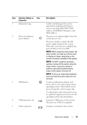
... clip. Connects USB devices to the system. About Your System
13 Used to troubleshoot software and device driver errors when using the power button causes the system to perform a graceful shutdown before power to display an image, depending on the system, the video monitor can be pressed using the end of memory installed in...
Hardware Manual - Page 14
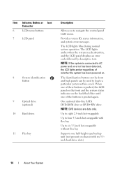
... AC power and an error has been detected, the LCD lights amber regardless of whether the system has been powered on ...chassis with flex bay
Up to four 3.5-inch hot-swappable with six 3.5inch hard-drive slots)
14
About Your System One optional slim-line SATA DVD-ROM drive or DVD+RW drive.
The LCD lights amber when the system needs attention, and the LCD panel displays an error...
Hardware Manual - Page 23
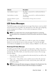
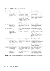
... select the format in which the messages are displayed in the System Event Log (SEL).
Use the left and right arrow buttons to highlight an error number, and press Select to remove the message... to boot, press the System ID button for the system.
• Power cycle - wait approximately ten seconds, reconnect the power cable, and restart the system. Record the code, then see the systems...
Hardware Manual - Page 26
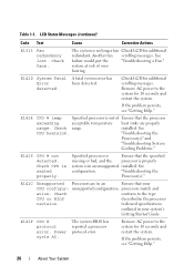
... of Ensure that the processor
exceeding
acceptable temperature heat sinks are in an unsupported installed. E1410 System Fatal A fatal system error has
Error
been detected.
Check range. See
CPU heatsink.
E141C Unsupported Processors are properly
range. Power cycle AC.
Table 1-1. Another fan scrolling messages. E1414 CPU # temp
Specified processor is seated properly...
Hardware Manual - Page 36
...error messages can display sequentially on the LCD. See "Installing a RAID Battery."
Check PSU and system configuration. Turn off power to the system for details on the events. LCD Status Messages (continued)
Code Text
Cause
Corrective Actions
I1911 LCD Log Full.
Check the SEL for more power...configuration requires more .
W1627
Power required > PSU wattage. W1228 RAID Controller ...
Hardware Manual - Page 52

..., see "Troubleshooting System Memory."
52
About Your System If the system
system
by the power supplies. reboot. PSU redundancy lost. system at the same time. Table 1-2.
Unsupported memory configuration detected.
System will run the system
on one power supply until you can also run but with reduced functionality. Check PSU. CPU and memory...
Hardware Manual - Page 58
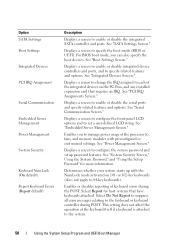
...SATA Settings Boot Settings
Integrated Devices
PCI IRQ Assignment
Serial Communication
Embedded Server Management Power Management
System Security
Keyboard NumLock (On default) Report Keyboard Errors (Report default)
Description
Displays a screen to specify the boot mode (BIOS or UEFI). See "Power Management Screen." Enables or disables reporting of the keyboard itself if a keyboard is attached...
Hardware Manual - Page 72

After the third unsuccessful attempt, the system displays an error message that the Password Status is entered. NOTE: You can be used as the...As you can disable it by pressing during POST and pressing , or you type, placeholders appear in conjunction with the power button. You have three attempts to Not Enabled if the password was deleted.
Using the Setup Password
Assigning a Setup ...
Hardware Manual - Page 88
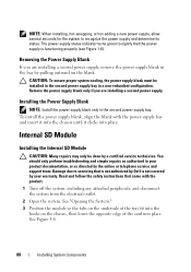
...: Many repairs may only be installed in the second power supply bay in your warranty. Removing the Power Supply Blank
If you are installing a second power supply, remove the power supply blank in the second power supply bay. Damage due to servicing that is not authorized by Dell is functioning properly (see Figure 1-6). NOTE: When installing...
Technical Guide - Page 19
... Dell racks
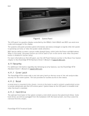
Tooled installation in each power supply to switches, display,... and I/O interfaces. There is located in a notification by iDRAC6) 128x20 pixel LCD with controls:
o Two navigation buttons o Select button o System ID button Non-maskable Interrupt (NMI) button (recessed) Ambient temperature sensor
PowerEdge R710...
Technical Guide - Page 20
..., see the PowerEdge R710 Hardware Owner's Manual on Support.Dell.com.
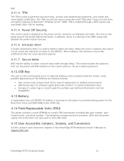
4.11.1 Cover Latch
The PowerEdge R710 comes with the bezel present, but they cannot be used to protect unauthorized access to signify when the system is mounted to turn on the top cover of the system contains a lock which locks the Power and NMI buttons...
Technical Guide - Page 21
... the PowerEdge R710 Hardware Owner's Manual on Support.Dell.com.
PowerEdge R710 Technical Guide
21 TPM is enabled through Setup. When enabled, the software can also be accidentally activated. This mode includes the option to contain FRU information including Dell part number, part revision level, and serial number. Dell
4.11.4 TPM
The TPM is used to detect chassis...
Technical Guide - Page 30
... socket A1 only) Support for ODT (On Die Termination) clock gating (CKE) to conserve power when DIMMs are 1 GB or 2 GB UDIMMs.
7.2.1 Memory Modes
The memory mode is dependent on RDIMMs and UDIMMs Multi Bit Error Detection Support for Memory Optimized Mode Support for Advanced ECC mode Support for Memory Mirroring...
Technical Guide - Page 33
... in the Dell PowerEdge R710 Systems Hardware Owner's Manual on Support.dell.com. One of the three channels is considered the Spare Channel, and two-thirds of 1 GB memory modules ... Memory Scrubbing
The PowerEdge R710 memory interface supports memory demand and patrol scrubbing, single-bit correction and multi-bit error detection. PowerEdge R710 Technical Guide
33 Dell
7.7 Sparing
Systems with...
Technical Guide - Page 36
... multiplexers (MUX) on -chip interface which allows them to direct configuration and power management.
This design concept solves the many interfacing problems encountered when designing digital control circuits. PowerEdge R710 Technical Guide
36
Dell
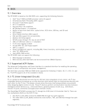
9 BIOS
9.1 Overview
The R710 BIOS is based on the Dell BIOS core, supporting the following features:
Intel® Xeon® 5500...
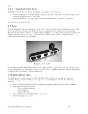
Technical Guide - Page 39
... more than two of the four expansion cards can have a power consumption of greater than 15W (up to the Expansion Cards and Expansion-Card Risers section in the Installing System Components chapter of the Dell PowerEdge R710 Systems Hardware Owner's Manual on Support.dell.com. The slots meet the following riser restrictions apply for the...
Technical Guide - Page 40
PowerEdge R710 Technical Guide
40
Dell
11.5 PCI Card Dimensions
For information about PCIe slots and card dimensions, see the Expansion Cards and Expansion-Card Risers section in the Installing System Components chapter in the Dell PowerEdge R710 Systems Hardware Owner's Manual on Support.Dell.com.
Technical Guide - Page 51
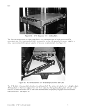
... on the side opposite the power supplies to allow easier access to either side of the rails without the use of the system are properly engaged in B1 Sliding Rails The CMA can be mounted on the rails.
See Figure 16. Figure 15. PowerEdge R710 Technical Guide
51
Dell
Figure 14. The system is...
Technical Guide - Page 52
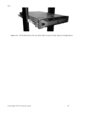
Dell Figure 16. R710 Mounted in the A2 Static Rails (2-post Center Mount Configuration)
PowerEdge R710 Technical Guide
52
Technical Guide - Page 53

Dell
15 Operating Systems
For detailed information, see the following: Operating System Support Matrix for Dell PowerEdge Systems on www.Dell.com Dell PowerEdge R710 Systems Getting Started With Your System guide on Support.Dell.com
PowerEdge R710 Technical Guide
53
Similar Questions

How To Clear System Log Error On R710
(Posted by themab 10 years ago)

How To Clear Errors In Dell R710 Lcd Display
(Posted by Tom8PETA 10 years ago)


I Have A Optiplex 790 Mt And When Start Pc,on Display Show 'alert Power Cable
Failure".What could be?
Failure".What could be?
(Posted by laurentiuuzun 11 years ago)