
Hardware Manual
Page 84
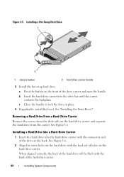
... drive at the back. a Press the button on the front of holes on the hard-drive carrier and separate the hard drive from the slide rails on the hard drive carrier. See "Installing the Front Bezel." Installing a Hot-Swap Hard Drive 1 2 1 release button 2 hard drive carrier handle 3 Install the hot-swap...
... drive at the back. a Press the button on the front of holes on the hard-drive carrier and separate the hard drive from the slide rails on the hard drive carrier. See "Installing the Front Bezel." Installing a Hot-Swap Hard Drive 1 2 1 release button 2 hard drive carrier handle 3 Install the hot-swap...
Hardware Manual
Page 108
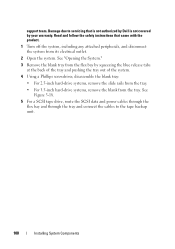
... the system, including any attached peripherals, and disconnect the system from the tray. Read and follow the safety instructions that is not authorized by Dell is not covered by squeezing the blue release tabs at the back of the tray and pushing the tray out of the system. 4 Using ...a Phillips screwdriver, disassemble the blank tray: • For 2.5-inch hard-drive systems, remove the slide rails from the tray. • For 3.5-inch hard-drive systems, remove the blank from its electrical outlet. 2 Open the system. See "Opening the System." 3 ...
... the system, including any attached peripherals, and disconnect the system from the tray. Read and follow the safety instructions that is not authorized by Dell is not covered by squeezing the blue release tabs at the back of the tray and pushing the tray out of the system. 4 Using ...a Phillips screwdriver, disassemble the blank tray: • For 2.5-inch hard-drive systems, remove the slide rails from the tray. • For 3.5-inch hard-drive systems, remove the blank from its electrical outlet. 2 Open the system. See "Opening the System." 3 ...

Hardware Manual
Page 109
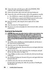
... installing a SCSI tape backup unit, install the SCSI controller expansion card in HDD Chassis Only) 2 3 1 4 1 drive blank 3 tray 2 screws (4) 4 tape backup unit 6 Install the slide rails or tray on the back of the expansion-card slots. Installing System Components 109 See "Installing an Expansion Card." 9 Connect the power cable to the...
... installing a SCSI tape backup unit, install the SCSI controller expansion card in HDD Chassis Only) 2 3 1 4 1 drive blank 3 tray 2 screws (4) 4 tape backup unit 6 Install the slide rails or tray on the back of the expansion-card slots. Installing System Components 109 See "Installing an Expansion Card." 9 Connect the power cable to the...
Hardware Manual
Page 110
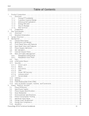
...the tape backup unit. 6 For a SCSI tape backup unit, disconnect the power and signal cables from the back of the unit. 7 Install the slide rails or the tray to the SCSI controller expansion card. a For a SCSI device, connect to the flex-bay blank. Damage due to servicing that came with... SATA device, connect to the SATA_B connector on the system. If replacing the tape backup unit, follow the safety instructions that is not authorized by Dell is not covered by a certified service technician. See Figure 6-2. 11 Connect the interface cable to the back of the tape backup unit. 12 Connect ...
...the tape backup unit. 6 For a SCSI tape backup unit, disconnect the power and signal cables from the back of the unit. 7 Install the slide rails or the tray to the SCSI controller expansion card. a For a SCSI device, connect to the flex-bay blank. Damage due to servicing that came with... SATA device, connect to the SATA_B connector on the system. If replacing the tape backup unit, follow the safety instructions that is not authorized by Dell is not covered by a certified service technician. See Figure 6-2. 11 Connect the interface cable to the back of the tape backup unit. 12 Connect ...
Technical Guide
Page 3
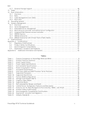
...IT Foundation 7 1.1.2 Customer-Inspired Design 7 1.1.3 Enhanced Virtualization 7 1.1.4 Energy Efficient 7 1.1.5 Easy to Manage 8 1.1.6 Dell Services 8 1.2 Comparison 8 2 Key Technologies 11 2.1 Overview 11 2.2 Detailed Information 11 3 System Overview 12 4 ...Supply Indicators 16 4.6 NIC Indicators 17 4.7 Internal Chassis Views 17 4.8 Rails and Cable Management 18 4.8.1 ReadyRails Sliding Rails 18 4.8.2 ReadyRails Static Rails 19 4.9 Fans ...19 4.10 LCD Control Panel 19 4.11 Security ... Compliance 25 5.10 Acoustics 25 PowerEdge R710 Technical Guidebook iii
...IT Foundation 7 1.1.2 Customer-Inspired Design 7 1.1.3 Enhanced Virtualization 7 1.1.4 Energy Efficient 7 1.1.5 Easy to Manage 8 1.1.6 Dell Services 8 1.2 Comparison 8 2 Key Technologies 11 2.1 Overview 11 2.2 Detailed Information 11 3 System Overview 12 4 ...Supply Indicators 16 4.6 NIC Indicators 17 4.7 Internal Chassis Views 17 4.8 Rails and Cable Management 18 4.8.1 ReadyRails Sliding Rails 18 4.8.2 ReadyRails Static Rails 19 4.9 Fans ...19 4.10 LCD Control Panel 19 4.11 Security ... Compliance 25 5.10 Acoustics 25 PowerEdge R710 Technical Guidebook iii
Technical Guide
Page 5
..., Acoustics and Hygienics 61 Industry Standards 62 PowerEdge R710 Technical Guidebook v Table 6. Table 17. Table 3. Table 12. Table 14. Table 4. Table 7. Dell 12.7 External Storage Support 46 13 Video...47 14 Rack Information 48 14.1 Overview 48 14.2 Rails ...48 14.3 Cable Management Arm (CMA 50... 14.4 Rack View 50 15 Operating Systems 53 16 Systems Management 54 16.1 Overview 54 16.2 Server Management 54 16.3 Embedded Server Management 55 16.4 Dell Lifecycle Controller and Unified Server ...
..., Acoustics and Hygienics 61 Industry Standards 62 PowerEdge R710 Technical Guidebook v Table 6. Table 17. Table 3. Table 12. Table 14. Table 4. Table 7. Dell 12.7 External Storage Support 46 13 Video...47 14 Rack Information 48 14.1 Overview 48 14.2 Rails ...48 14.3 Cable Management Arm (CMA 50... 14.4 Rack View 50 15 Operating Systems 53 16 Systems Management 54 16.1 Overview 54 16.2 Server Management 54 16.3 Embedded Server Management 55 16.4 Dell Lifecycle Controller and Unified Server ...

Technical Guide
Page 6
Figure 5. Figure 9. Figure 12. Figure 3. Figure 7. Figure 10. Figure 16. Figure 14. Dell Figure 1. Figure 15. Figure 13. Figure 2. Figure 6. Figure 8. Figure 4. Figure 11. Figures Chassis Dimensions 15 Front View (3.5‖ Hard Drive...Memory Channels 31 R710 Sliding Rails with Optional CMA 48 2U Threaded Rack Adapter Brackets Kit 49 R710 Static Rails 49 R710 Mounted in B1 Sliding Rails 51 R710 Mounted in the B1 Sliding Rails with the CMA 51 R710 Mounted in the A2 Static Rails (2-post Center Mount Configuration 52 PowerEdge R710 Technical Guidebook vi
Figure 5. Figure 9. Figure 12. Figure 3. Figure 7. Figure 10. Figure 16. Figure 14. Dell Figure 1. Figure 15. Figure 13. Figure 2. Figure 6. Figure 8. Figure 4. Figure 11. Figures Chassis Dimensions 15 Front View (3.5‖ Hard Drive...Memory Channels 31 R710 Sliding Rails with Optional CMA 48 2U Threaded Rack Adapter Brackets Kit 49 R710 Static Rails 49 R710 Mounted in B1 Sliding Rails 51 R710 Mounted in the B1 Sliding Rails with the CMA 51 R710 Mounted in the A2 Static Rails (2-post Center Mount Configuration 52 PowerEdge R710 Technical Guidebook vi
Technical Guide
Page 14
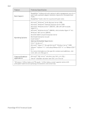
PowerEdge R710 Technical Guide 14 Featured Database Applications Microsoft® SQL Server® solutions (see Dell.com/SQL) Oracle® database solutions (see Dell.com/Oracle) 1GB means 1 billion bytes and TB equals 1 trillion bytes; actual capacity varies with optional cable ... (including VMware ESX® 4.1 or VMware ESXi™ 4.1) For more information on the specific versions and additions, visit www.dell.com/OSsupport. Dell Feature Technical Specification Rack Support ReadyRails™ sliding rails with preloaded material and operating environment and will be less.
PowerEdge R710 Technical Guide 14 Featured Database Applications Microsoft® SQL Server® solutions (see Dell.com/SQL) Oracle® database solutions (see Dell.com/Oracle) 1GB means 1 billion bytes and TB equals 1 trillion bytes; actual capacity varies with optional cable ... (including VMware ESX® 4.1 or VMware ESXi™ 4.1) For more information on the specific versions and additions, visit www.dell.com/OSsupport. Dell Feature Technical Specification Rack Support ReadyRails™ sliding rails with preloaded material and operating environment and will be less.
Technical Guide
Page 18
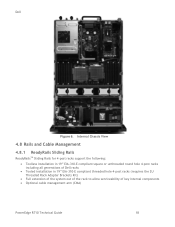
... of Dell racks Tooled installation in 19‖ EIA-310-E compliant threaded hole 4-post racks (requires the 2U Threaded Rack Adapter Brackets Kit) Full extension of the system out of the rack to allow serviceability of key internal components Optional cable management arm (CMA) PowerEdge R710 Technical Guide 18 Dell Figure...
... of Dell racks Tooled installation in 19‖ EIA-310-E compliant threaded hole 4-post racks (requires the 2U Threaded Rack Adapter Brackets Kit) Full extension of the system out of the rack to allow serviceability of key internal components Optional cable management arm (CMA) PowerEdge R710 Technical Guide 18 Dell Figure...
Technical Guide
Page 19
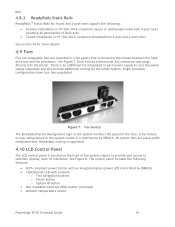
... are mounted in a fan gantry that plugs directly into the planar. Single processor configurations have four fans populated. Dell 4.8.2 ReadyRails Static Rails ReadyRailsTM Static Rails for 4-post and 2-post racks support the following features: ACPI-compliant power button with controls: o Two... Non-maskable Interrupt (NMI) button (recessed) Ambient temperature sensor PowerEdge R710 Technical Guide 19 Each fan has a blind mate 2x2 connector that is located on the front of Dell racks Tooled installation in 19‖ EIA-310-E compliant threaded hole ...
... are mounted in a fan gantry that plugs directly into the planar. Single processor configurations have four fans populated. Dell 4.8.2 ReadyRails Static Rails ReadyRailsTM Static Rails for 4-post and 2-post racks support the following features: ACPI-compliant power button with controls: o Two... Non-maskable Interrupt (NMI) button (recessed) Ambient temperature sensor PowerEdge R710 Technical Guide 19 Each fan has a blind mate 2x2 connector that is located on the front of Dell racks Tooled installation in 19‖ EIA-310-E compliant threaded hole ...
Technical Guide
Page 48
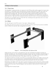
... the system to be fully extended out of the rack used in order to close the door of Dell racks. R710 Sliding Rails with square or unthreaded round mounting holes including all generations of the rack. PowerEdge R710 Technical Guide 48 The optional cable management arm (CMA) can be mounted on the depth of the...
... the system to be fully extended out of the rack used in order to close the door of Dell racks. R710 Sliding Rails with square or unthreaded round mounting holes including all generations of the rack. PowerEdge R710 Technical Guide 48 The optional cable management arm (CMA) can be mounted on the depth of the...

Technical Guide
Page 49
... the 2U Threaded Rack Adapter Brackets Kit (Dell part number PKCR1) PowerEdge R710 Technical Guide 49 Dell Figure 12. 2U Threaded Rack Adapter Brackets Kit The static rails support a wider variety of rack in which they will be installed. R710 Static Rails One key factor in selecting the proper rails is identifying the type of racks than the...
... the 2U Threaded Rack Adapter Brackets Kit (Dell part number PKCR1) PowerEdge R710 Technical Guide 49 Dell Figure 12. 2U Threaded Rack Adapter Brackets Kit The static rails support a wider variety of rack in which they will be installed. R710 Static Rails One key factor in selecting the proper rails is identifying the type of racks than the...
Technical Guide
Page 50
... power distribution units (PDUs), and the overall depth of thread designations. Other key factors governing proper rail selection include the spacing between the front and rear mounting flanges in threaded or 2-post racks. PowerEdge R710 Technical Guide 50 Dell Screws are not included in the static rail kit because threaded racks are offered with the...
... power distribution units (PDUs), and the overall depth of thread designations. Other key factors governing proper rail selection include the spacing between the front and rear mounting flanges in threaded or 2-post racks. PowerEdge R710 Technical Guide 50 Dell Screws are not included in the static rail kit because threaded racks are offered with the...
Technical Guide
Page 51
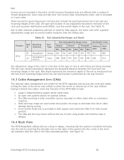
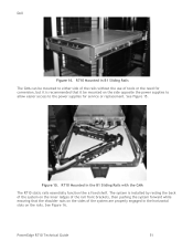
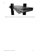
... the B1 Sliding Rails with the CMA The R710 static rails essentially function like a fixed shelf. See Figure 16. PowerEdge R710 Technical Guide 51 Figure 15. R710 Mounted in B1 Sliding Rails The CMA can be mounted to either side of the rails without the use of the system are properly engaged in the horizontal ...See Figure 15. The system is recommended that it is installed by resting the back of the system on the inner ledges of the rail front brackets, then pushing the system forward while ensuring that the shoulder nuts on the sides of tools or the need for conversion, but...
... the B1 Sliding Rails with the CMA The R710 static rails essentially function like a fixed shelf. See Figure 16. PowerEdge R710 Technical Guide 51 Figure 15. R710 Mounted in B1 Sliding Rails The CMA can be mounted to either side of the rails without the use of the system are properly engaged in the horizontal ...See Figure 15. The system is recommended that it is installed by resting the back of the system on the inner ledges of the rail front brackets, then pushing the system forward while ensuring that the shoulder nuts on the sides of tools or the need for conversion, but...
Technical Guide
Page 52
R710 Mounted in the A2 Static Rails (2-post Center Mount Configuration) PowerEdge R710 Technical Guide 52 Dell Figure 16.
R710 Mounted in the A2 Static Rails (2-post Center Mount Configuration) PowerEdge R710 Technical Guide 52 Dell Figure 16.