
Hardware Manual
Page 7
... 107 Installing the Tape Backup Unit 107 Removing the Tape Backup Unit 110 Integrated Storage Controller Card 111 Removing the Integrated Storage Controller Card 112 Installing the Integrated Storage Controller Card 112 RAID Battery 116 Removing a RAID Battery 116 Installing a RAID Battery 117 Cable Routing 118 Removing the Cable Retention Bracket 118 Installing the Cable Retention...
... 107 Installing the Tape Backup Unit 107 Removing the Tape Backup Unit 110 Integrated Storage Controller Card 111 Removing the Integrated Storage Controller Card 112 Installing the Integrated Storage Controller Card 112 RAID Battery 116 Removing a RAID Battery 116 Installing a RAID Battery 117 Cable Routing 118 Removing the Cable Retention Bracket 118 Installing the Cable Retention...
Hardware Manual
Page 8
... Modules 136 Processors 137 Removing a Processor 137 Installing a Processor 140 System Battery 141 Replacing the System Battery 141 Control Panel Assembly 143 Removing the Control Panel Display Module . . . 143 Installing the Control Panel Display Module . . . . 143 Removing the Control Panel Board 144 Installing the Control Panel Board 145 SAS Backplane 146 Removing the SAS Backplane 146 Installing...
... Modules 136 Processors 137 Removing a Processor 137 Installing a Processor 140 System Battery 141 Replacing the System Battery 141 Control Panel Assembly 143 Removing the Control Panel Display Module . . . 143 Installing the Control Panel Display Module . . . . 143 Removing the Control Panel Board 144 Installing the Control Panel Board 145 SAS Backplane 146 Removing the SAS Backplane 146 Installing...
Hardware Manual
Page 9
...Battery 158 Troubleshooting Power Supplies 158 Troubleshooting System Cooling Problems 159 Troubleshooting a Fan 160 Troubleshooting System Memory 160 Troubleshooting an Internal SD Card 162 Troubleshooting an Internal USB Memory Key . . . . . 163 Troubleshooting an Optical Drive 164 Troubleshooting a Tape Backup Unit 165 Troubleshooting a Hard Drive 166 Troubleshooting a Storage Controller... 167 Troubleshooting Expansion Cards 168 Troubleshooting the Processor(s 170 5 Running the System Diagnostics . . . . . 173 Using Dell™ PowerEdge™ Diagnostics...
...Battery 158 Troubleshooting Power Supplies 158 Troubleshooting System Cooling Problems 159 Troubleshooting a Fan 160 Troubleshooting System Memory 160 Troubleshooting an Internal SD Card 162 Troubleshooting an Internal USB Memory Key . . . . . 163 Troubleshooting an Optical Drive 164 Troubleshooting a Tape Backup Unit 165 Troubleshooting a Hard Drive 166 Troubleshooting a Storage Controller... 167 Troubleshooting Expansion Cards 168 Troubleshooting the Processor(s 170 5 Running the System Diagnostics . . . . . 173 Using Dell™ PowerEdge™ Diagnostics...
Hardware Manual
Page 24
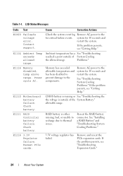
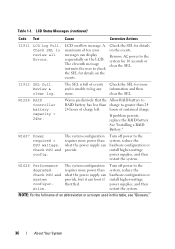
...unable to recharge due to the for critical failure events. LCD Status Messages Code Text E1000 Failsafe voltage error. Check battery. E1216 3.3V Regulator failure. Problems." Memory has exceeded allowable temperature and has been disabled to prevent damage to ...see "Troubleshooting Expansion Cards." 24 About Your System Check battery. Cause Corrective Actions Check the system event log Remove AC power to thermal issues. Table 1-1. Contact support. E1210 Motherboard battery failure. E1211 RAID Controller battery failure. system for 10 seconds and restart the system...
...unable to recharge due to the for critical failure events. LCD Status Messages Code Text E1000 Failsafe voltage error. Check battery. E1216 3.3V Regulator failure. Problems." Memory has exceeded allowable temperature and has been disabled to prevent damage to ...see "Troubleshooting Expansion Cards." 24 About Your System Check battery. Cause Corrective Actions Check the system event log Remove AC power to thermal issues. Table 1-1. Contact support. E1210 Motherboard battery failure. E1211 RAID Controller battery failure. system for 10 seconds and restart the system...
Hardware Manual
Page 36
...power than what the power supply can display sequentially on the events. If problem persists, replace the RAID battery. The system configuration requires more . NOTE: For the full name of sustained charge. hours of an...the user to the system for details on the LCD. Warns predictively that the Allow RAID battery to RAID battery has less than 24 24 hours of events and is unable to log any more power...Text Cause Corrective Actions I1911 LCD Log Full. W1228 RAID Controller battery capacity < 24hr. W1628 Performance degraded. Check PSU and system configuration.
...power than what the power supply can display sequentially on the events. If problem persists, replace the RAID battery. The system configuration requires more . NOTE: For the full name of sustained charge. hours of an...the user to the system for details on the LCD. Warns predictively that the Allow RAID battery to RAID battery has less than 24 24 hours of events and is unable to log any more power...Text Cause Corrective Actions I1911 LCD Log Full. W1228 RAID Controller battery capacity < 24hr. W1628 Performance degraded. Check PSU and system configuration.
Hardware Manual
Page 76
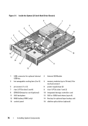
... hot-swappable cooling fans (4 or 5) 5 processors (1 or 2) 7 riser 2 (PCIe slots 3 and 4) 9 iDRAC6 Enterprise card (optional) 11 SAS backplane 13 RAID battery (PERC only) 15 control panel 2 Internal SD Module 4 memory modules (up to 18 total, 9 for each processor) 6 power supply bays (2) 8 riser 1 (PCIe slots 1 and 2) 10... integrated storage controller card 12 SAS or SATA hard drives (up to 8) 14 flex bay for optional tape backup unit 16 ...
... hot-swappable cooling fans (4 or 5) 5 processors (1 or 2) 7 riser 2 (PCIe slots 3 and 4) 9 iDRAC6 Enterprise card (optional) 11 SAS backplane 13 RAID battery (PERC only) 15 control panel 2 Internal SD Module 4 memory modules (up to 18 total, 9 for each processor) 6 power supply bays (2) 8 riser 1 (PCIe slots 1 and 2) 10... integrated storage controller card 12 SAS or SATA hard drives (up to 8) 14 flex bay for optional tape backup unit 16 ...
Hardware Manual
Page 112
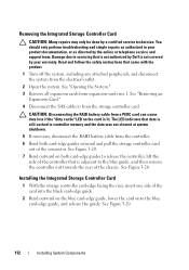
... cleared at system shutdown. 5 If necessary, disconnect the RAID battery cable from the controller. 6 Bend both card-edge guides to the blue guide, and then remove the controller out towards the rear of the controller that is not authorized by Dell is lit. CAUTION: Disconnecting the RAID battery cable from the electrical outlet. 2 Open the system.
... cleared at system shutdown. 5 If necessary, disconnect the RAID battery cable from the controller. 6 Bend both card-edge guides to the blue guide, and then remove the controller out towards the rear of the controller that is not authorized by Dell is lit. CAUTION: Disconnecting the RAID battery cable from the electrical outlet. 2 Open the system.
Hardware Manual
Page 113
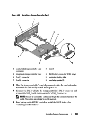
... labels on the riser until the card is fully seated. Installing a Storage Controller Card 2 1 3 4 5 8 7 6 1 dedicated storage controller card connector 3 integrated storage controller card 5 SAS_1 connector 7 SAS_0 connector 2 riser 1 4 RAID battery connector (PERC only) 6 connector locking tabs 8 card edge guides (2) 3 Slide the storage controller's card edge connector into the card slot on the cable. Figure 3-20...
... labels on the riser until the card is fully seated. Installing a Storage Controller Card 2 1 3 4 5 8 7 6 1 dedicated storage controller card connector 3 integrated storage controller card 5 SAS_1 connector 7 SAS_0 connector 2 riser 1 4 RAID battery connector (PERC only) 6 connector locking tabs 8 card edge guides (2) 3 Slide the storage controller's card edge connector into the card slot on the cable. Figure 3-20...
Hardware Manual
Page 114
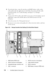
... already done, route the interface and RAID battery cables in Hard-Drive Chassis) 1 2 3 45 6 78 1 RAID battery (PERC only) 3 SAS A connector on backplane 5 integrated storage controller card 7 SAS_1 connector 2 SAS B connector on backplane 4 cable retention bracket 6 SAS_0 connector 8 RAID battery connector (PERC only) 114 Installing System Components Storage Controller Card Cabling (2.5-in the cable path...
... already done, route the interface and RAID battery cables in Hard-Drive Chassis) 1 2 3 45 6 78 1 RAID battery (PERC only) 3 SAS A connector on backplane 5 integrated storage controller card 7 SAS_1 connector 2 SAS B connector on backplane 4 cable retention bracket 6 SAS_0 connector 8 RAID battery connector (PERC only) 114 Installing System Components Storage Controller Card Cabling (2.5-in the cable path...
Hardware Manual
Page 115
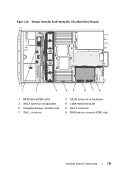
Figure 3-22. Storage Controller Card Cabling (Six 3.5-in Hard-Drive Chassis) 1 2 3 45 6 78 1 RAID battery (PERC only) 3 SAS A connector on backplane 5 integrated storage controller card 7 SAS_1 connector 2 SAS B connector on backplane 4 cable retention bracket 6 SAS_0 connector 8 RAID battery connector (PERC only) Installing System Components 115
Figure 3-22. Storage Controller Card Cabling (Six 3.5-in Hard-Drive Chassis) 1 2 3 45 6 78 1 RAID battery (PERC only) 3 SAS A connector on backplane 5 integrated storage controller card 7 SAS_1 connector 2 SAS B connector on backplane 4 cable retention bracket 6 SAS_0 connector 8 RAID battery connector (PERC only) Installing System Components 115
Hardware Manual
Page 116
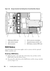
... the right edge of the battery bay and draw out the RAID battery from the battery carrier. 2 Disconnect the cable between the RAID battery and the storage controller card. See Figure 3-24. 116 Installing System Components Removing a RAID Battery 1 Pull back gently on backplane 4 integrated storage controller card 6 RAID battery connector (PERC only) RAID Battery The information in this...
... the right edge of the battery bay and draw out the RAID battery from the battery carrier. 2 Disconnect the cable between the RAID battery and the storage controller card. See Figure 3-24. 116 Installing System Components Removing a RAID Battery 1 Pull back gently on backplane 4 integrated storage controller card 6 RAID battery connector (PERC only) RAID Battery The information in this...
Hardware Manual
Page 117
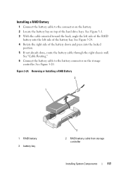
.... Installing a RAID Battery 1 Connect the battery cable to the battery connector on top of the battery down and press into the left side of the RAID battery into the locked position. 5 If not already done, route the battery cable through the right chassis wall. Removing or Installing a RAID Battery 2 1 1 RAID battery 3 battery bay 3 2 RAID battery cable from storage controller Installing System...
.... Installing a RAID Battery 1 Connect the battery cable to the battery connector on top of the battery down and press into the left side of the RAID battery into the locked position. 5 If not already done, route the battery cable through the right chassis wall. Removing or Installing a RAID Battery 2 1 1 RAID battery 3 battery bay 3 2 RAID battery cable from storage controller Installing System...
Hardware Manual
Page 151
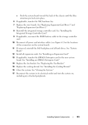
... Components 151 c Push the system board toward the back of the connectors on , including any attached peripherals. See "Installing the Integrated Storage Controller Card." 9 If applicable, reconnect the RAID battery cable to its electrical outlet and turn the system on the system board). 11 If removed, reinstall the SAS backplane and all...
... Components 151 c Push the system board toward the back of the connectors on , including any attached peripherals. See "Installing the Integrated Storage Controller Card." 9 If applicable, reconnect the RAID battery cable to its electrical outlet and turn the system on the system board). 11 If removed, reinstall the SAS backplane and all...
Hardware Manual
Page 168
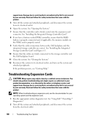
... Storage Controller Card." 8 If you have a battery-cached PERC controller, ensure that the RAID battery is properly connected and, if applicable, the memory module on the system and attached peripherals. support team. See "Opening the System." 7 Ensure that is not authorized by Dell is properly... are correct. See "Closing the System." 12 Reconnect the system to servicing that the controller card is not covered by a certified service technician. See "Using Dell™ PowerEdge™ Diagnostics." 2 Turn off the system and attached peripherals, and disconnect the system ...
... Storage Controller Card." 8 If you have a battery-cached PERC controller, ensure that the RAID battery is properly connected and, if applicable, the memory module on the system and attached peripherals. support team. See "Opening the System." 7 Ensure that is not authorized by Dell is properly... are correct. See "Closing the System." 12 Reconnect the system to servicing that the controller card is not covered by a certified service technician. See "Using Dell™ PowerEdge™ Diagnostics." 2 Turn off the system and attached peripherals, and disconnect the system ...
Hardware Manual
Page 181
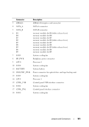
... 3 iDRAC6 4 SATA_A 5 SATA_B 6 B1 B4 B7 B2 B5 B8 B3 B6 B9 7 FAN5 8 BP_PWR 9 CPU2 10 FAN4 11 BATTERY 12 DVD/TBU_PWR 13 FAN3 14 CPU1 15 CTRL_USB 16 FAN2 17 CTRL_PNL 18 FAN1 Description iDRAC6 Enterprise card connector SATA A connector SATA B ...memory module slot B6 memory module slot B9 System cooling fan Backplane power connector Processor 2 System cooling fan System battery Power connector for optical drive and tape backup unit System cooling fan Processor 1 Control panel USB interface connector System cooling fan Control panel interface connector System cooling fan Jumpers and Connectors 181
... 3 iDRAC6 4 SATA_A 5 SATA_B 6 B1 B4 B7 B2 B5 B8 B3 B6 B9 7 FAN5 8 BP_PWR 9 CPU2 10 FAN4 11 BATTERY 12 DVD/TBU_PWR 13 FAN3 14 CPU1 15 CTRL_USB 16 FAN2 17 CTRL_PNL 18 FAN1 Description iDRAC6 Enterprise card connector SATA A connector SATA B ...memory module slot B6 memory module slot B9 System cooling fan Backplane power connector Processor 2 System cooling fan System battery Power connector for optical drive and tape backup unit System cooling fan Processor 1 Control panel USB interface connector System cooling fan Control panel interface connector System cooling fan Jumpers and Connectors 181

Hardware Manual
Page 198
... DDR3 memory module. A port on the devices or by the number of pixels up and down. A battery-powered unit that automatically supplies power to the network controller. USB - A USB connector provides a single connection point for example) is expressed as the number of colors... provides (in the configuration software for example. USB memory key - utility - V - The logical circuitry that offloads network processing to your system's RAM. video memory - Terabyte(s); 1024 gigabytes or 1,099,511,627,776 bytes. termination - Some devices (such as mice and keyboards. uplink port ...
... DDR3 memory module. A port on the devices or by the number of pixels up and down. A battery-powered unit that automatically supplies power to the network controller. USB - A USB connector provides a single connection point for example) is expressed as the number of colors... provides (in the configuration software for example. USB memory key - utility - V - The logical circuitry that offloads network processing to your system's RAM. video memory - Terabyte(s); 1024 gigabytes or 1,099,511,627,776 bytes. termination - Some devices (such as mice and keyboards. uplink port ...
Hardware Manual
Page 201
...battery (RAID) installing, 116 removing, 116 battery (system) replacing, 141 troubleshooting, 158 BIOS boot mode, 55 blank hard drive, 81 power supply, 88 boot mode, 55 C cable retention bracket installing, 119 removing, 118 cable routing, 118 cabling cable routing, 118 optical drive, 103 storage controller... board, 182 serial, 20 system board, 180 USB, 12 video, 12 contacting Dell, 189 control panel assembly features, 12 LCD panel features, 15 control panel board installing, 145 removing, 144 control panel display module installing, 143 removing, 143 cooling fan removing, 100 replacing, 101...
...battery (RAID) installing, 116 removing, 116 battery (system) replacing, 141 troubleshooting, 158 BIOS boot mode, 55 blank hard drive, 81 power supply, 88 boot mode, 55 C cable retention bracket installing, 119 removing, 118 cable routing, 118 cabling cable routing, 118 optical drive, 103 storage controller... board, 182 serial, 20 system board, 180 USB, 12 video, 12 contacting Dell, 189 control panel assembly features, 12 LCD panel features, 15 control panel board installing, 145 removing, 144 control panel display module installing, 143 removing, 143 cooling fan removing, 100 replacing, 101...
Hardware Manual
Page 203
... PCIe expansion cards, 120 power supply blank, 88 processor, 140 RAID battery, 116-117 riser 2 into expansion-card bracket, 128 SAS backplane board, 147 SD card, 90 storage controller, 112 tape backup unit, 107 VFlash SD card, 96 Integrated Dell Remote Access Controller See iDRAC6 Enterprise card. internal SD flash card installing, 90 internal...
... PCIe expansion cards, 120 power supply blank, 88 processor, 140 RAID battery, 116-117 riser 2 into expansion-card bracket, 128 SAS backplane board, 147 SD card, 90 storage controller, 112 tape backup unit, 107 VFlash SD card, 96 Integrated Dell Remote Access Controller See iDRAC6 Enterprise card. internal SD flash card installing, 90 internal...
Hardware Manual
Page 205
... 88 processor installing, 140 removing, 137 troubleshooting, 170 upgrades, 137 PSU See power supply. R RAID battery installing, 117 removing, 116 removing cable retention bracket, 118 control panel board, 144 control panel display module, 143 cooling fan, 100 cooling shroud, 99 expansion-card riser 1, 123 expansion-card ...drive blank, 81 hard drive from a drive carrier, 84 hard drives, 82 iDRAC6 Enterprise card, 95 information tag, 78 integrated storage controller, 112 internal SD flash card, 90 internal SD module, 90 internal USB cable, 93 memory modules, 136 optical drive, 104 PCIe expansion...
... 88 processor installing, 140 removing, 137 troubleshooting, 170 upgrades, 137 PSU See power supply. R RAID battery installing, 117 removing, 116 removing cable retention bracket, 118 control panel board, 144 control panel display module, 143 cooling fan, 100 cooling shroud, 99 expansion-card riser 1, 123 expansion-card ...drive blank, 81 hard drive from a drive carrier, 84 hard drives, 82 iDRAC6 Enterprise card, 95 information tag, 78 integrated storage controller, 112 internal SD flash card, 90 internal SD module, 90 internal USB cable, 93 memory modules, 136 optical drive, 104 PCIe expansion...

Hardware Manual
Page 207
... key, 163 keyboard, 154 memory, 160 NIC, 155 optical drive, 164 PCIe expansion cards, 168 power supplies, 158 processor(s), 170 SD card, 162 storage controller, 167 system battery, 158 system cooling, 159 system startup failure, 153 tape backup unit, 165 video, 154 wet system, 156 U UEFI Boot Manager entering, 68 main screen...
... key, 163 keyboard, 154 memory, 160 NIC, 155 optical drive, 164 PCIe expansion cards, 168 power supplies, 158 processor(s), 170 SD card, 162 storage controller, 167 system battery, 158 system cooling, 159 system startup failure, 153 tape backup unit, 165 video, 154 wet system, 156 U UEFI Boot Manager entering, 68 main screen...


