User Manual
Page 1
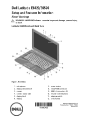
camera 4. eSata/USB connector 9. wireless switch 12. Front View 1. display release latch 3. Latitude E6420 Front And Back View Figure 1. USB 2.0 connectors (2) 10. camera status light 5. display 7. volume control buttons 11. Dell Latitude E6420/E6520 Setup and Features Information About Warnings WARNING: A WARNING indicates a potential for property damage, personal injury, or death. microphone 2. power button 8. display latch 6. optical drive Regulatory Model: P15G, P14F Regulatory Type: P15G001, P14F001 February 2011
camera 4. eSata/USB connector 9. wireless switch 12. Front View 1. display release latch 3. Latitude E6420 Front And Back View Figure 1. USB 2.0 connectors (2) 10. camera status light 5. display 7. volume control buttons 11. Dell Latitude E6420/E6520 Setup and Features Information About Warnings WARNING: A WARNING indicates a potential for property damage, personal injury, or death. microphone 2. power button 8. display latch 6. optical drive Regulatory Model: P15G, P14F Regulatory Type: P15G001, P14F001 February 2011
User Manual
Page 2
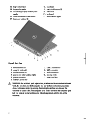
... not indicate a problem with the fan or the computer. 2 Fan noise is running. contactless smart card reader 17. Do not store your Dell computer in the air vents. trackstick buttons (3) 20. trackstick 21. Back View 1. The computer turns on the fan when the computer gets hot. touchpad buttons (2) 18. power and battery status lights 5. VGA connector 9. touchpad 19. cooling vents 11. modem connector 4. fingerprint reader 15. device status lights Figure...
... not indicate a problem with the fan or the computer. 2 Fan noise is running. contactless smart card reader 17. Do not store your Dell computer in the air vents. trackstick buttons (3) 20. trackstick 21. Back View 1. The computer turns on the fan when the computer gets hot. touchpad buttons (2) 18. power and battery status lights 5. VGA connector 9. touchpad 19. cooling vents 11. modem connector 4. fingerprint reader 15. device status lights Figure...
User Manual
Page 3
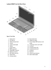
... release latch 4. power button 8. HDMI connector 9. wireless switch 14. trackstick buttons (3) 21. keyboard 23. camera 5. optical drive 13. Front View 1. microphone 3. touchpad 19. Secure Digital (SD) memory-card reader 17. trackstick 22. device status lights 3 ExpressCard slot 15. display 7. USB 2.0 connector 11. fingerprint reader 16. display latch 2. camera status light 6. IEEE 1394 connector 12. touchpad buttons (2) 20. volume control buttons 24. contactless smart card reader 18. eSata/USB connector 10. Latitude E6520 Front And Back...
... release latch 4. power button 8. HDMI connector 9. wireless switch 14. trackstick buttons (3) 21. keyboard 23. camera 5. optical drive 13. Front View 1. microphone 3. touchpad 19. Secure Digital (SD) memory-card reader 17. trackstick 22. device status lights 3 ExpressCard slot 15. display 7. USB 2.0 connector 11. fingerprint reader 16. display latch 2. camera status light 6. IEEE 1394 connector 12. touchpad buttons (2) 20. volume control buttons 24. contactless smart card reader 18. eSata/USB connector 10. Latitude E6520 Front And Back...

Owners Manual
Page 7
33 Display Panel 113 Removing the Display Panel 113 Installing the Display Panel 115 34 Display Bracket 117 Removing the Display Bracket 117 Installing the Display Bracket 117 35 Camera 119 Removing the Camera 119 Installing the Camera...120 36 Specifications 121 Technical Specifications 121 37 System Setup 129 Setup Overview...129 Entering System Setup 129 System Setup Menu...129 38 Diagnostics 141 Diagnostic LED Codes 141 Battery Status Lights...142 Device Status Lights...143 39 Contacting Dell 145 Contacting Dell...145
33 Display Panel 113 Removing the Display Panel 113 Installing the Display Panel 115 34 Display Bracket 117 Removing the Display Bracket 117 Installing the Display Bracket 117 35 Camera 119 Removing the Camera 119 Installing the Camera...120 36 Specifications 121 Technical Specifications 121 37 System Setup 129 Setup Overview...129 Entering System Setup 129 System Setup Menu...129 38 Diagnostics 141 Diagnostic LED Codes 141 Battery Status Lights...142 Device Status Lights...143 39 Contacting Dell 145 Contacting Dell...145
Owners Manual
Page 11
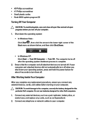
... telephone or network cables to your computer. 1. Connect any external devices, cards, and cables before you shut down the operating system: • In Windows Vista : Click Start , then click the arrow in the lower-right corner of the Start menu as an ExpressCard. 2. Ensure that the computer and all open programs before turning on your operating system, press and hold the power button for this particular Dell computer. CAUTION...
... telephone or network cables to your computer. 1. Connect any external devices, cards, and cables before you shut down the operating system: • In Windows Vista : Click Start , then click the arrow in the lower-right corner of the Start menu as an ExpressCard. 2. Ensure that the computer and all open programs before turning on your operating system, press and hold the power button for this particular Dell computer. CAUTION...

Owners Manual
Page 121
... External bus frequency • Intel Core i3 series (available only with Latitude E6420 only) • Intel Core i5 series with Turbo Boost technology 2.0 • Intel Core i7 series with your computer. For more information regarding the configuration of your computer, click Start → Help and Support and select the option to 6 MB 1333 MHz Memory Memory connector Memory capacity Memory type Minimum memory Maximum memory two SODIMM slots...
... External bus frequency • Intel Core i3 series (available only with Latitude E6420 only) • Intel Core i5 series with Turbo Boost technology 2.0 • Intel Core i7 series with your computer. For more information regarding the configuration of your computer, click Start → Help and Support and select the option to 6 MB 1333 MHz Memory Memory connector Memory capacity Memory type Minimum memory Maximum memory two SODIMM slots...
Owners Manual
Page 122
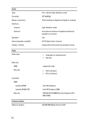
Audio Type Controller Stereo conversion Interface: Internal External Speakers Internal speaker amplifier Volume controls Video Video type Data bus: UMA Discrete Controller: UMA Latitude E6420 Latitude E6420 ATG Discrete Communications Network adapter four-channel high definition audio IDT 92HD90 24-bit (analog-to-digital and digital-to-analog) high definition audio microphone-in/stereo headphones/external speakers connector two 0.5 W (typical) per channel keyboard function keys and program menus • integrated on system board • discrete integrated video •...
Audio Type Controller Stereo conversion Interface: Internal External Speakers Internal speaker amplifier Volume controls Video Video type Data bus: UMA Discrete Controller: UMA Latitude E6420 Latitude E6420 ATG Discrete Communications Network adapter four-channel high definition audio IDT 92HD90 24-bit (analog-to-digital and digital-to-analog) high definition audio microphone-in/stereo headphones/external speakers connector two 0.5 W (typical) per channel keyboard function keys and program menus • integrated on system board • discrete integrated video •...
Owners Manual
Page 132
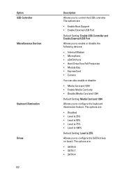
The options are : • Enable Boot Support • Enable External USB Port Default Setting: Enable USB Controller and Enable External USB Port Allows you to enable or disable the following devices: • Internal Modem • Microphone • eSATA Ports • Hard Drive Free Fall Protection • Module Bay • ExpressCard • Camera You can also enable or disable: • Media Card and 1394 • Enable Media Card only • Disable Media Card and 1394 Default Setting: Media Card and 1394 Allows you to configure the keyboard illumination feature. The options are: ...
The options are : • Enable Boot Support • Enable External USB Port Default Setting: Enable USB Controller and Enable External USB Port Allows you to enable or disable the following devices: • Internal Modem • Microphone • eSATA Ports • Hard Drive Free Fall Protection • Module Bay • ExpressCard • Camera You can also enable or disable: • Media Card and 1394 • Enable Media Card only • Disable Media Card and 1394 Default Setting: Media Card and 1394 Allows you to configure the keyboard illumination feature. The options are: ...
Owners Manual
Page 138
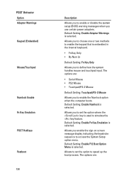
... embedded in the internal keyboard. • Fn Key Only • By Num Lk Default Setting: Fn Key Only Allows you to enable or disable the system setup (BIOS) warning messages when you use certain power adapters. Allows you to choose one or two methods to enable the keypad that is used to access the System Setup option menu. POST Behavior Option Adapter Warnings Keypad (Embedded) Mouse/Touchpad Numlock Enable Fn Key Emulation POST HotKeys Fastboot 138...
... embedded in the internal keyboard. • Fn Key Only • By Num Lk Default Setting: Fn Key Only Allows you to enable or disable the system setup (BIOS) warning messages when you use certain power adapters. Allows you to choose one or two methods to enable the keypad that is used to access the System Setup option menu. POST Behavior Option Adapter Warnings Keypad (Embedded) Mouse/Touchpad Numlock Enable Fn Key Emulation POST HotKeys Fastboot 138...
Administration Guide
Page 5
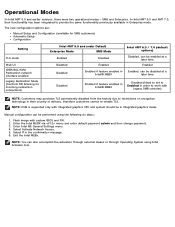
NOTE: KVM is supported only with system BIOS and FW. 2. Manual configuration can be disabled at a later time Disabled Enabled if feature enabled in Intel® MEBX Disabled (Need to set to Enabled in order to work with Legacy SMB consoles) NOTE: Customers may purchase TLS permanently disabled from the factory due to provide the same functionality previously available in integrated graphics mode. Select Activate Network Access. 5. The new configuration options are: Manual Setup and Configuration (available for...
NOTE: KVM is supported only with system BIOS and FW. 2. Manual configuration can be disabled at a later time Disabled Enabled if feature enabled in Intel® MEBX Disabled (Need to set to Enabled in order to work with Legacy SMB consoles) NOTE: Customers may purchase TLS permanently disabled from the factory due to provide the same functionality previously available in integrated graphics mode. Select Activate Network Access. 5. The new configuration options are: Manual Setup and Configuration (available for...
Administration Guide
Page 6
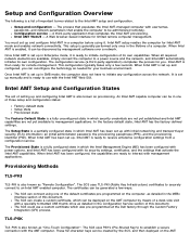
... be discovered by means of a desk-side visit with the Intel AMT Web GUI. In the factory-default state, Intel AMT has the factory-defined settings. The SCS could use with a specially formatted USB thumb drive as needed for limited remote computer management. These 52-character keys can be created by the SCS, and then deployed on the AMT computer by management software over a network.
... be discovered by means of a desk-side visit with the Intel AMT Web GUI. In the factory-default state, Intel AMT has the factory-defined settings. The SCS could use with a specially formatted USB thumb drive as needed for limited remote computer management. These 52-character keys can be created by the SCS, and then deployed on the AMT computer by management software over a network.
Administration Guide
Page 15
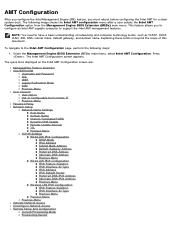
... to support the Intel AMT management features. NOTE: You need to the Intel AMT Configuration page, perform the following image shows the Intel AMT configuration menu after a user selects the Intel AMT Configuration option from remote IT Previous Menu Password Policy Network Setup Network Name Settings Host Name Domain Name Shared / Dedicated FQDN Dynamic DNS Update Periodic Update Interval TTL Previous Menu TCP/IP Settings Wired LAN IPv4 Configuration DHCP Mode IPv4...
... to support the Intel AMT management features. NOTE: You need to the Intel AMT Configuration page, perform the following image shows the Intel AMT configuration menu after a user selects the Intel AMT Configuration option from remote IT Previous Menu Password Policy Network Setup Network Name Settings Host Name Domain Name Shared / Dedicated FQDN Dynamic DNS Update Periodic Update Interval TTL Previous Menu TCP/IP Settings Wired LAN IPv4 Configuration DHCP Mode IPv4...
Administration Guide
Page 37
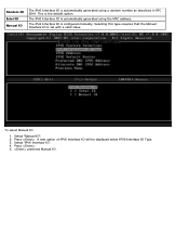
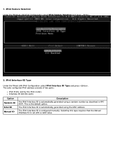
Select "Manual ID". 2. This is set with a valid value. Selecting this type requires that the Manual Interface ID is the default option. The IPv6 Interface ID is configured manually. A new option of IPV6 Interface ID will be displayed below IPV6 Interface ID Type. 3. Press . 5. Select 'IPV6 Interface ID'. 4. preferred Manual ID. Press . To select Manual ID 1. The IPv6 Interface ID is automatically generated using a random number as described in RFC 3041. Random ID Intel ID Manual ID The IPv6 Interface ID is automatically generated using the MAC address.
Select "Manual ID". 2. This is set with a valid value. Selecting this type requires that the Manual Interface ID is the default option. The IPv6 Interface ID is configured manually. A new option of IPV6 Interface ID will be displayed below IPV6 Interface ID Type. 3. Press . 5. Select 'IPV6 Interface ID'. 4. preferred Manual ID. Press . To select Manual ID 1. The IPv6 Interface ID is automatically generated using a random number as described in RFC 3041. Random ID Intel ID Manual ID The IPv6 Interface ID is automatically generated using the MAC address.
Administration Guide
Page 41
... configured manually. Selecting this type requires that the Manual Interface ID is the default option. The IPv6 Interface ID is automatically generated using a random number as described in RFC 3041. The IPv6 Interface ID is automatically generated using the MAC address. 1. The auto-configured IPv6 address consists of two parts: IPv6 Prefix (set with a valid value. IPv6 Feature Selection Under the Wireless LAN IPv6 Configuration...
... configured manually. Selecting this type requires that the Manual Interface ID is the default option. The IPv6 Interface ID is automatically generated using a random number as described in RFC 3041. The IPv6 Interface ID is automatically generated using the MAC address. 1. The auto-configured IPv6 address consists of two parts: IPv6 Prefix (set with a valid value. IPv6 Feature Selection Under the Wireless LAN IPv6 Configuration...
Administration Guide
Page 64
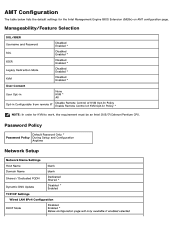
... Default Password Only * Password Policy During Setup and Configuration Anytime Network Setup Network Name Settings Host Name blank Domain Name blank Shared / Dedicated FQDN Dedicated Shared * Dynamic DNS Update Disabled * Enabled TCP/IP Settings Wired LAN IPv4 Configuration DHCP Mode Disabled Enabled * Below configuration page will only available if enabled selected AMT Configuration The table below lists the default settings for KVM to work, the requirement must be an Intel i3/i5/i7/Celeron/Pentium CPU. Manageability...
... Default Password Only * Password Policy During Setup and Configuration Anytime Network Setup Network Name Settings Host Name blank Domain Name blank Shared / Dedicated FQDN Dedicated Shared * Dynamic DNS Update Disabled * Enabled TCP/IP Settings Wired LAN IPv4 Configuration DHCP Mode Disabled Enabled * Below configuration page will only available if enabled selected AMT Configuration The table below lists the default settings for KVM to work, the requirement must be an Intel i3/i5/i7/Celeron/Pentium CPU. Manageability...
Administration Guide
Page 67
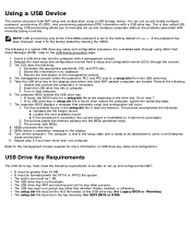
... the factory default by clearing the CMOS. The process accomplishes the following : 1. Repeat step 5 if you to users in the top directory (for more than 16 MB. Using a USB Device This section discusses Intel AMT setup and configuration using Altiris Dell Client Manager (DCM), refer to step 7. You can set up and locally configure password, provisioning ID (PID), and provisioning passphrase (PPS) information with manually typing in the USB drive key...
... the factory default by clearing the CMOS. The process accomplishes the following : 1. Repeat step 5 if you to users in the top directory (for more than 16 MB. Using a USB Device This section discusses Intel AMT setup and configuration using Altiris Dell Client Manager (DCM), refer to step 7. You can set up and locally configure password, provisioning ID (PID), and provisioning passphrase (PPS) information with manually typing in the USB drive key...
Administration Guide
Page 100
... can be manually entered into the Intel AMT capable computer's MEBx. Intel Active Management Technology (Intel AMT) does not work with the username and password and provisions the following information: Provisioning ID (PID) Universally Unique Identifier (UUID) IP address ROM and firmware (FW) version numbers The Hello message is used for a Setup and Configuration Server (SCS). In the AMT 7, in the network. For...
... can be manually entered into the Intel AMT capable computer's MEBx. Intel Active Management Technology (Intel AMT) does not work with the username and password and provisions the following information: Provisioning ID (PID) Universally Unique Identifier (UUID) IP address ROM and firmware (FW) version numbers The Hello message is used for a Setup and Configuration Server (SCS). In the AMT 7, in the network. For...

Administration Guide
Page 101
... AMT Serial-Over-LAN (SOL) / Local Manageability Service (LMS) driver is available on support.dell.com and on the ResourceCD under Chipset Drivers. The Intel AMT Host Embedded Controller Interface (HECI) driver is labeled Intel AMT SOL/LMS. Install the driver by double-clicking on the installer. Once you install the SOL/LMS driver, the PCI Serial Port entry becomes the Intel Active Management Technology - The driver is available on support.dell...
... AMT Serial-Over-LAN (SOL) / Local Manageability Service (LMS) driver is available on support.dell.com and on the ResourceCD under Chipset Drivers. The Intel AMT Host Embedded Controller Interface (HECI) driver is labeled Intel AMT SOL/LMS. Install the driver by double-clicking on the installer. Once you install the SOL/LMS driver, the PCI Serial Port entry becomes the Intel Active Management Technology - The driver is available on support.dell...
Administration Guide
Page 102
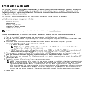
Limited remote computer management includes: Hardware inventory Event logging Remote computer reset Changing of network settings Addition of new users NOTE: Information on using the WebUI interface is changed . Type the username and password. Changing the password in the WebUI or a remote console results in the WebUI. The local MEBx password used , then use the fully qualified domain name (FQDN) for the ME. If the remote password is available...
Limited remote computer management includes: Hardware inventory Event logging Remote computer reset Changing of network settings Addition of new users NOTE: Information on using the WebUI interface is changed . Type the username and password. Changing the password in the WebUI or a remote console results in the WebUI. The local MEBx password used , then use the fully qualified domain name (FQDN) for the ME. If the remote password is available...
Administration Guide
Page 107
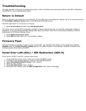
.... If this setting is passed back to factory defaults and does not reset ME configuration settings or passwords. Serial-Over-LAN (SOL) / IDE Redirection (IDE-R) If you cannot use IDE-R and SOL, perform these steps: 1. An Intel AMT setup and configured computer can be un-provisioned using the Unconfigure Network Access option on the ME General Settings screen. Select Return to enter the MEBx screens. 2. Type the new Intel ME password. 3. Follow the...
.... If this setting is passed back to factory defaults and does not reset ME configuration settings or passwords. Serial-Over-LAN (SOL) / IDE Redirection (IDE-R) If you cannot use IDE-R and SOL, perform these steps: 1. An Intel AMT setup and configured computer can be un-provisioned using the Unconfigure Network Access option on the ME General Settings screen. Select Return to enter the MEBx screens. 2. Type the new Intel ME password. 3. Follow the...


