User Manual
Page 1
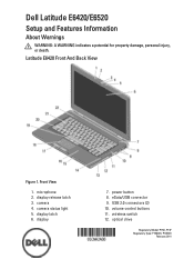
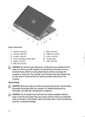
Front View 1. display latch 6. display 7. volume control buttons 11. camera status light 5. eSata/USB connector 9. wireless switch 12. optical drive Regulatory Model: P15G, P14F Regulatory Type: P15G001, P14F001 February 2011 display release latch 3. microphone 2. power button 8. USB 2.0 connectors (2) 10. camera 4. Dell Latitude E6420/E6520 Setup and Features Information About Warnings WARNING: A WARNING indicates a potential for property damage, personal injury, or death. Latitude E6420 Front And Back View Figure 1.
Front View 1. display latch 6. display 7. volume control buttons 11. camera status light 5. eSata/USB connector 9. wireless switch 12. optical drive Regulatory Model: P15G, P14F Regulatory Type: P15G001, P14F001 February 2011 display release latch 3. microphone 2. power button 8. USB 2.0 connectors (2) 10. camera 4. Dell Latitude E6420/E6520 Setup and Features Information About Warnings WARNING: A WARNING indicates a potential for property damage, personal injury, or death. Latitude E6420 Front And Back View Figure 1.
User Manual
Page 2
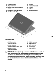
ExpressCard slot 14. touchpad buttons (2) 18. trackstick 21. modem connector 4. Do not store your Dell computer in the air vents. The computer turns on the fan when the computer gets hot. fingerprint reader 15. security cable slot 3.... or cause a fire. trackstick buttons (3) 20. device status lights Figure 2. VGA connector 9. Fan noise is running. touchpad 19. power and battery status lights 5. USB 2.0 connector 8. audio connector 10. 13. HDMI connector 2. cooling vents 11. Secure Digital (SD) memory-card reader 16. keyboard 22. Back View 1. smart card...
ExpressCard slot 14. touchpad buttons (2) 18. trackstick 21. modem connector 4. Do not store your Dell computer in the air vents. The computer turns on the fan when the computer gets hot. fingerprint reader 15. security cable slot 3.... or cause a fire. trackstick buttons (3) 20. device status lights Figure 2. VGA connector 9. Fan noise is running. touchpad 19. power and battery status lights 5. USB 2.0 connector 8. audio connector 10. 13. HDMI connector 2. cooling vents 11. Secure Digital (SD) memory-card reader 16. keyboard 22. Back View 1. smart card...
User Manual
Page 3
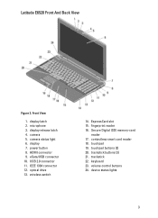
.... device status lights 3 power button 8. wireless switch 14. Secure Digital (SD) memory-card reader 17. touchpad buttons (2) 20. Latitude E6520 Front And Back View Figure 3. camera 5. fingerprint reader 16. microphone 3. camera status light 6. USB 2.0 connector 11. volume control buttons 24. optical drive 13. touchpad 19. trackstick 22. keyboard 23. Front View 1. display 7.
.... device status lights 3 power button 8. wireless switch 14. Secure Digital (SD) memory-card reader 17. touchpad buttons (2) 20. Latitude E6520 Front And Back View Figure 3. camera 5. fingerprint reader 16. microphone 3. camera status light 6. USB 2.0 connector 11. volume control buttons 24. optical drive 13. touchpad 19. trackstick 22. keyboard 23. Front View 1. display 7.
User Manual
Page 4
...shipped with electrical outlets worldwide. For additional best practices information, see www.dell.com/regulatory_compliance. The computer turns on the fan when the computer gets hot. WARNING: The AC adapter works... with your Dell computer in the air vents. power and battery status lights 5. power connector 6. cooling vents 11... problem with the fan or the computer. Back View 1. audio connector 10. USB 2.0 connector 9. Figure 4. security cable slot 3. USB 2.0 connector 7. Fan noise is running.
...shipped with electrical outlets worldwide. For additional best practices information, see www.dell.com/regulatory_compliance. The computer turns on the fan when the computer gets hot. WARNING: The AC adapter works... with your Dell computer in the air vents. power and battery status lights 5. power connector 6. cooling vents 11... problem with the fan or the computer. Back View 1. audio connector 10. USB 2.0 connector 9. Figure 4. security cable slot 3. USB 2.0 connector 7. Fan noise is running.
User Manual
Page 5
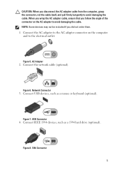
... you wrap the AC adapter cable, ensure that you follow the angle of the connector on the computer and to avoid damaging the cable. Connect USB devices, such as a 1394 hard drive (optional). Figure 8. 1394 Connector 5 CAUTION: When you did not order them. 1. Connect the AC adapter to the AC adapter...
... you wrap the AC adapter cable, ensure that you follow the angle of the connector on the computer and to avoid damaging the cable. Connect USB devices, such as a 1394 hard drive (optional). Figure 8. 1394 Connector 5 CAUTION: When you did not order them. 1. Connect the AC adapter to the AC adapter...
Owners Manual
Page 123
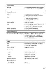
... connector • one 15-pin VGA connector • one 19-pin HDMI connector one RJ-45 connector three 4-pin USB 2.0-compliant connectors and one eSATA/USB 2.0-compliant connector one 5-in-1 memory card reader Contactless Smart Card Supported Smart Cards/Technologies ISO14443A - 106 kbps, 212 kbps...kbps, and 848 kbps ISO15693 HID iClass FIPS201 NXP Desfire Display Type Size Active area (X/Y) Dimensions: Height Width Diagonal Maximum resolution Maximum Brightness Latitude E6420 white Light Emitting Diode (WLED) display 14.0 inch high definition (HD) 309.40 mm x 173.95 mm 192.50 mm (7....
... connector • one 15-pin VGA connector • one 19-pin HDMI connector one RJ-45 connector three 4-pin USB 2.0-compliant connectors and one eSATA/USB 2.0-compliant connector one 5-in-1 memory card reader Contactless Smart Card Supported Smart Cards/Technologies ISO14443A - 106 kbps, 212 kbps...kbps, and 848 kbps ISO15693 HID iClass FIPS201 NXP Desfire Display Type Size Active area (X/Y) Dimensions: Height Width Diagonal Maximum resolution Maximum Brightness Latitude E6420 white Light Emitting Diode (WLED) display 14.0 inch high definition (HD) 309.40 mm x 173.95 mm 192.50 mm (7....
Owners Manual
Page 130
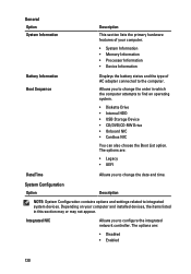
The options are : • Legacy • UEFI Date/Time Allows you to find an operating system. • Diskette Drive • Internal HDD • USB Storage Device • CD/DVD/CD-RW Drive • Onboard NIC • Cardbus NIC You can also choose the Boot List option. Depending on your ...
The options are : • Legacy • UEFI Date/Time Allows you to find an operating system. • Diskette Drive • Internal HDD • USB Storage Device • CD/DVD/CD-RW Drive • Onboard NIC • Cardbus NIC You can also choose the Boot List option. Depending on your ...
Owners Manual
Page 132
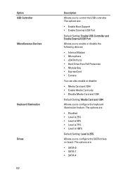
... Card and 1394 • Enable Media Card only • Disable Media Card and 1394 Default Setting: Media Card and 1394 Allows you to control the USB controller. The options are: • Disabled • Level is 25% • Level is 50% • Level is 75% • Level is 100% Default Setting:... Level is 25% Allows you to configure the keyboard illumination feature. The options are : • SATA-0 • SATA-1 • SATA-4 Option USB Controller Miscellaneous Devices Keyboard illumination Drives 132 Description Allows you to configure the SATA drives on board.
... Card and 1394 • Enable Media Card only • Disable Media Card and 1394 Default Setting: Media Card and 1394 Allows you to control the USB controller. The options are: • Disabled • Level is 25% • Level is 50% • Level is 75% • Level is 100% Default Setting:... Level is 25% Allows you to configure the keyboard illumination feature. The options are : • SATA-0 • SATA-1 • SATA-4 Option USB Controller Miscellaneous Devices Keyboard illumination Drives 132 Description Allows you to configure the SATA drives on board.
Owners Manual
Page 136
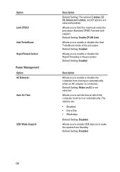
...: The options C states, C3, C6, Enhanced C-states, and C7 options are : • Disabled • Every Day • Weekdays Default Setting: Disabled Allows you to enable USB devices to enable or disable the computer from Standby. Allows you to enable or disable the HyperThreading in the processor. Default Setting: Wake on automatically...
...: The options C states, C3, C6, Enhanced C-states, and C7 options are : • Disabled • Every Day • Weekdays Default Setting: Disabled Allows you to enable USB devices to enable or disable the computer from Standby. Allows you to enable or disable the HyperThreading in the processor. Default Setting: Wake on automatically...
Owners Manual
Page 137
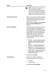
... field allows the computer to be powered on by this setting and must be powered on when it receives a wakeup signal from all of the USB ports to AC. • Disabled - Allows the system to power up from wired or wireless networks without depending on LAN/WLAN ExpressCharge Description NOTE: This...
... field allows the computer to be powered on by this setting and must be powered on when it receives a wakeup signal from all of the USB ports to AC. • Disabled - Allows the system to power up from wired or wireless networks without depending on LAN/WLAN ExpressCharge Description NOTE: This...
Owners Manual
Page 142
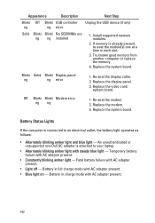
... Blinki Display panel ng ng error 1. Off Blinki Blinki Modem error ng ng 1. Replace the system board. An unauthenticated or unsupported non-Dell AC adapter is already present, re-seat the module(s) one at a time in each slot. 3. Battery in full charge mode with AC... system board. Temporary battery failure with AC adapter present. • Light off - Appearance Description Next Step Blinki Off Blinki USB controller ng ng error Unplug the USB device (if any) Solid Blinki Blinki No SODIMMs are ng ng installed 1. Install supported memory modules. 2. Re-seat the ...
... Blinki Display panel ng ng error 1. Off Blinki Blinki Modem error ng ng 1. Replace the system board. An unauthenticated or unsupported non-Dell AC adapter is already present, re-seat the module(s) one at a time in each slot. 3. Battery in full charge mode with AC... system board. Temporary battery failure with AC adapter present. • Light off - Appearance Description Next Step Blinki Off Blinki USB controller ng ng error Unplug the USB device (if any) Solid Blinki Blinki No SODIMMs are ng ng installed 1. Install supported memory modules. 2. Re-seat the ...

Administration Guide
Page 1
...for use of these materials in this text: Dell™, the DELL logo, Dell Precision™, Precision ON™, ExpressCharge™, Latitude™, Latitude ON™, OptiPlex™, Vostro™, and Wi-Fi Catcher™ are trademarks of Dell Inc. and any use on discs and ...Other trademarks and trade names may be used in this document to either trademarks or registered trademarks of Dell Inc. Using a USB Device Configuration Service - A00 USB Device Procedure System Deployment Operating System Drivers Management Intel AMT Web GUI AMT Redirection (SOL/IDE-R) AMT...
...for use of these materials in this text: Dell™, the DELL logo, Dell Precision™, Precision ON™, ExpressCharge™, Latitude™, Latitude ON™, OptiPlex™, Vostro™, and Wi-Fi Catcher™ are trademarks of Dell Inc. and any use on discs and ...Other trademarks and trade names may be used in this document to either trademarks or registered trademarks of Dell Inc. Using a USB Device Configuration Service - A00 USB Device Procedure System Deployment Operating System Drivers Management Intel AMT Web GUI AMT Redirection (SOL/IDE-R) AMT...
Administration Guide
Page 6
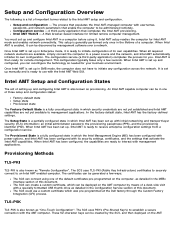
... AMT is set up with management applications. Once Intel AMT is enabled, it is a partially configured state in which was pre-programmed at the Dell factory through the Custom Factory Integration (CFI) process. The SCS uses PSK's (Pre-Shared Key's) to establish a secure connection with usernames, passwords...set up in Enterprise mode, it can be deployed on the AMT computer by means of a desk-side visit with a specially formatted USB thumb drive as detailed in the MEBx interface section of three setup and configuration states: Factory-default state Setup state Provisioned state The ...
... AMT is set up with management applications. Once Intel AMT is enabled, it is a partially configured state in which was pre-programmed at the Dell factory through the Custom Factory Integration (CFI) process. The SCS uses PSK's (Pre-Shared Key's) to establish a secure connection with usernames, passwords...set up in Enterprise mode, it can be deployed on the AMT computer by means of a desk-side visit with a specially formatted USB thumb drive as detailed in the MEBx interface section of three setup and configuration states: Factory-default state Setup state Provisioned state The ...

Administration Guide
Page 7
The SCS can create a list of two ways: The key can be manually typed into the MEBx. computer with a desk-side visit in the Configuration Service section of this document. Then each AMT computer retrieves a custom key from the specially formatted USB thumb drive during BIOS boot as detailed in one of custom keys, and put them onto a specially formatted USB thumb drive.
The SCS can create a list of two ways: The key can be manually typed into the MEBx. computer with a desk-side visit in the Configuration Service section of this document. Then each AMT computer retrieves a custom key from the specially formatted USB thumb drive during BIOS boot as detailed in one of custom keys, and put them onto a specially formatted USB thumb drive.

Administration Guide
Page 66
... be listed within the Intel Management Engine BIOS Extension (MEBx). *TLS-PKI refer as Remote Configuration (RCFG) or Zero Touch Configuration (ZTC). Commonly referred to a USB mass storage device. Methods Overview As discussed in the next section.
... be listed within the Intel Management Engine BIOS Extension (MEBx). *TLS-PKI refer as Remote Configuration (RCFG) or Zero Touch Configuration (ZTC). Commonly referred to a USB mass storage device. Methods Overview As discussed in the next section.
Administration Guide
Page 67
... Intel AMT setup and configuration using Altiris Dell Client Manager (DCM), refer to a setup.bin file in the USB drive key. 5. This is a typical USB drive key setup and configuration procedure. USB provisioning allows you have more information on the USB drive key (for Legacy BIOS or Wembley...It must be greater than one computer. You can set up and configure computers without the problems associated with a management console. 2. NOTE: USB provisioning only works if the MEBx password is read into a computer. 3. The SCS does the following requirements to be in the setup state...
... Intel AMT setup and configuration using Altiris Dell Client Manager (DCM), refer to a setup.bin file in the USB drive key. 5. This is a typical USB drive key setup and configuration procedure. USB provisioning allows you have more information on the USB drive key (for Legacy BIOS or Wembley...It must be greater than one computer. You can set up and configure computers without the problems associated with a management console. 2. NOTE: USB provisioning only works if the MEBx password is read into a computer. 3. The SCS does the following requirements to be in the setup state...

Administration Guide
Page 68
...and seen by double-clicking the desktop icon or through third-party vendors. Open the Altiris Dell Client Manager application by the DNS server before you begin this process. USB Device Procedure Dell Client Management (DCM) application is not always dynamic or real time. Select AMT Quick ...Start from the left navigation menu to the requirements listed on Using a USB Device page. Format a USB device with the DCM package. The ...
...and seen by double-clicking the desktop icon or through third-party vendors. Open the Altiris Dell Client Manager application by the DNS server before you begin this process. USB Device Procedure Dell Client Management (DCM) application is not always dynamic or real time. Select AMT Quick ...Start from the left navigation menu to the requirements listed on Using a USB Device page. Format a USB device with the DCM package. The ...
Administration Guide
Page 85
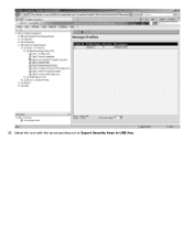
23. Select the icon with the arrow pointing out to Export Security Keys to USB Key.
23. Select the icon with the arrow pointing out to Export Security Keys to USB Key.

Administration Guide
Page 88
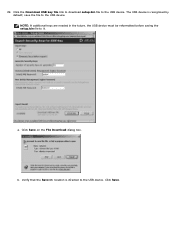
Click Generate. Insert the previously formatted USB device into a USB connector on the ProvisioningServer. 27. Once the keys have been created, a link appears to the left of the Generate button. 28.
Click Generate. Insert the previously formatted USB device into a USB connector on the ProvisioningServer. 27. Once the keys have been created, a link appears to the left of the Generate button. 28.
Administration Guide
Page 89
Click Save. a. Click Save on the File Download dialog box. b. Click the Download USB key file link to download setup.bin file to the USB device. 29. NOTE: If additional keys are needed in : location is recognized by default; Verify that the Save in the future, the USB device must be reformatted before saving the setup.bin file to the USB device. save the file to the USB device. The USB device is directed to it.
Click Save. a. Click Save on the File Download dialog box. b. Click the Download USB key file link to download setup.bin file to the USB device. 29. NOTE: If additional keys are needed in : location is recognized by default; Verify that the Save in the future, the USB device must be reformatted before saving the setup.bin file to the USB device. save the file to the USB device. The USB device is directed to it.


