Specifications (SWF/PDF)
Page 5
... Assembly 57 Removing the Power-Button Assembly 57 Replacing the Power-Button Assembly 59 21 Processor Heat-Sink 61 Removing the Processor Heat-Sink 61 Replacing the Processor Heat-Sink 63 22 Processor 65 Removing the ...
... Assembly 57 Removing the Power-Button Assembly 57 Replacing the Power-Button Assembly 59 21 Processor Heat-Sink 61 Removing the Processor Heat-Sink 61 Replacing the Processor Heat-Sink 63 22 Processor 65 Removing the ...
Specifications (SWF/PDF)
Page 7
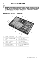
... shipped with your computer and follow the steps in "Before You Begin" on page 11. Inside View of Your Computer 3 2 1 4 5 6 7 14 13 8 12 9 11 10 1 power-button board 3 optical-drive assembly 5 fan 7 memory module(s) 9 system board 11 wireless Mini-Card 13 hard-drive assembly 2 chassis 4 converter board 6 processor heat-sink 8 coin... TV-tuner card (optional) 12 B-CAS card (Japan only) 14 speakers (2) Technical Overview | 7 For additional safety best practices information, see the Regulatory Compliance Homepage at dell.com/regulatory_compliance.
... shipped with your computer and follow the steps in "Before You Begin" on page 11. Inside View of Your Computer 3 2 1 4 5 6 7 14 13 8 12 9 11 10 1 power-button board 3 optical-drive assembly 5 fan 7 memory module(s) 9 system board 11 wireless Mini-Card 13 hard-drive assembly 2 chassis 4 converter board 6 processor heat-sink 8 coin... TV-tuner card (optional) 12 B-CAS card (Japan only) 14 speakers (2) Technical Overview | 7 For additional safety best practices information, see the Regulatory Compliance Homepage at dell.com/regulatory_compliance.
Specifications (SWF/PDF)
Page 9
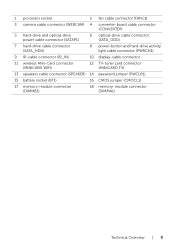
... 2 fan cable connector (FANC1) 3 camera cable connector (WEBCAM) 4 converter-board cable connector (CONVERTER) 5 hard-drive and optical-drive power cable connector (SATAP1) 6 optical-drive cable connector (SATA_ODD) 7 hard-drive cable connector (SATA_HDD) 8 power-button and hard-drive activity light cable connector (PWRCN1) 9 IR-cable connector (IR_IN) 10 display-cable connector 11 wireless...
... 2 fan cable connector (FANC1) 3 camera cable connector (WEBCAM) 4 converter-board cable connector (CONVERTER) 5 hard-drive and optical-drive power cable connector (SATAP1) 6 optical-drive cable connector (SATA_ODD) 7 hard-drive cable connector (SATA_HDD) 8 power-button and hard-drive activity light cable connector (PWRCN1) 9 IR-cable connector (IR_IN) 10 display-cable connector 11 wireless...
Specifications (SWF/PDF)
Page 11
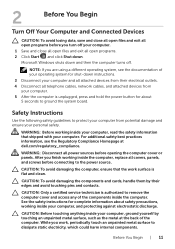
... avoid damaging the components and cards, handle them by touching an unpainted metal surface, such as the metal at dell.com/regulatory_compliance. WARNING: Disconnect all attached devices from potential damage and ensure your operating system for complete information about ... ensure that shipped with your computer, and protecting against electrostatic discharge. WARNING: Before working inside your computer and all power sources before connecting to dissipate static electricity, which could harm internal components. For additional safety best practices information, see ...
... avoid damaging the components and cards, handle them by touching an unpainted metal surface, such as the metal at dell.com/regulatory_compliance. WARNING: Disconnect all attached devices from potential damage and ensure your operating system for complete information about ... ensure that shipped with your computer, and protecting against electrostatic discharge. WARNING: Before working inside your computer and all power sources before connecting to dissipate static electricity, which could harm internal components. For additional safety best practices information, see ...

Specifications (SWF/PDF)
Page 22
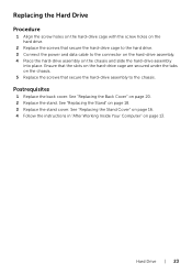
Procedure 1 Remove the screws that secure the hard-drive assembly to the chassis. 2 Slide and lift the hard-drive assembly and then disconnect the power and data cable from the connector on the hard drive. 2 3 4 1 1 chassis 3 hard-drive assembly 2 screw (3) 4 power and data cable 3 Remove the screws that secure the hard-drive cage to the hard drive. 4 Lift the hard-drive cage off the hard drive. 1 hard-drive cage 3 screws (4) 1 23 2 hard drive 22 | Hard Drive
Procedure 1 Remove the screws that secure the hard-drive assembly to the chassis. 2 Slide and lift the hard-drive assembly and then disconnect the power and data cable from the connector on the hard drive. 2 3 4 1 1 chassis 3 hard-drive assembly 2 screw (3) 4 power and data cable 3 Remove the screws that secure the hard-drive cage to the hard drive. 4 Lift the hard-drive cage off the hard drive. 1 hard-drive cage 3 screws (4) 1 23 2 hard drive 22 | Hard Drive
Specifications (SWF/PDF)
Page 23
...-drive cage are secured under the tabs on the chassis. 5 Replace the screws that secure the hard-drive cage to the hard drive. 3 Connect the power and data cable to the chassis. See "Replacing the Stand Cover" on page 16. 4 Follow the instructions in "After Working Inside Your Computer" on page...
...-drive cage are secured under the tabs on the chassis. 5 Replace the screws that secure the hard-drive cage to the hard drive. 3 Connect the power and data cable to the chassis. See "Replacing the Stand Cover" on page 16. 4 Follow the instructions in "After Working Inside Your Computer" on page...
Specifications (SWF/PDF)
Page 25
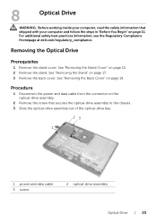
...information that secures the optical-drive assembly to the chassis. 3 Slide the optical-drive assembly out of the optical-drive bay. 23 1 1 power and data cable 3 screw 2 optical-drive assembly Optical Drive | 25 Removing the Optical Drive Prerequisites 1 Remove the stand cover. See "...the Stand Cover" on page 17. 3 Remove the back cover. For additional safety best practices information, see the Regulatory Compliance Homepage at dell.com/regulatory_compliance. See "Removing the Back Cover" on page 11. 8 Optical Drive WARNING: Before working inside your computer and follow the...
...information that secures the optical-drive assembly to the chassis. 3 Slide the optical-drive assembly out of the optical-drive bay. 23 1 1 power and data cable 3 screw 2 optical-drive assembly Optical Drive | 25 Removing the Optical Drive Prerequisites 1 Remove the stand cover. See "...the Stand Cover" on page 17. 3 Remove the back cover. For additional safety best practices information, see the Regulatory Compliance Homepage at dell.com/regulatory_compliance. See "Removing the Back Cover" on page 11. 8 Optical Drive WARNING: Before working inside your computer and follow the...
Specifications (SWF/PDF)
Page 26
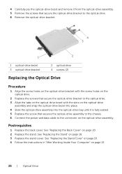
... assembly into the optical-drive bay until it is fully seated. 5 Replace the screw that secures the optical-drive assembly to the chassis. 6 Connect the power and data cable to the connector on page 20. 2 Replace the stand. See "Replacing the Back Cover" on the optical-drive assembly. Postrequisites 1 Replace the...
... assembly into the optical-drive bay until it is fully seated. 5 Replace the screw that secures the optical-drive assembly to the chassis. 6 Connect the power and data cable to the connector on page 20. 2 Replace the stand. See "Replacing the Back Cover" on the optical-drive assembly. Postrequisites 1 Replace the...
Specifications (SWF/PDF)
Page 57
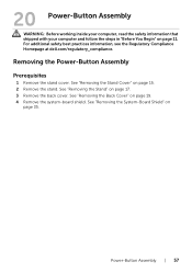
For additional safety best practices information, see the Regulatory Compliance Homepage at dell.com/regulatory_compliance. See "Removing the Stand" on page 11. Power-Button Assembly | 57 20 Power-Button Assembly WARNING: Before working inside your computer, read the safety information that shipped with your computer and ... in "Before You Begin" on page 17. 3 Remove the back cover. See "Removing the Back Cover" on page 35. Removing the Power-Button Assembly Prerequisites 1 Remove the stand cover. See "Removing the System-Board Shield" on page 19. 4 Remove the system-board shield. ...
For additional safety best practices information, see the Regulatory Compliance Homepage at dell.com/regulatory_compliance. See "Removing the Stand" on page 11. Power-Button Assembly | 57 20 Power-Button Assembly WARNING: Before working inside your computer, read the safety information that shipped with your computer and ... in "Before You Begin" on page 17. 3 Remove the back cover. See "Removing the Back Cover" on page 35. Removing the Power-Button Assembly Prerequisites 1 Remove the stand cover. See "Removing the System-Board Shield" on page 19. 4 Remove the system-board shield. ...
Specifications (SWF/PDF)
Page 58
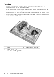
Procedure 1 Disconnect the power-button and hard-drive activity light cable from the connector (PWRCN1) on the system board. 2 Make a note of the power-button and hard-drive activity light cable routing and remove it from the routing guides. 3 Remove the screw that secures the power-button assembly to the middle frame. 4 Slide the power-button assembly toward the top of the computer and then lift it away from the middle frame. 1 2 3 1 screw 2 power-button assembly 3 power-button and hard-drive activity light cable 58 | Power-Button Assembly
Procedure 1 Disconnect the power-button and hard-drive activity light cable from the connector (PWRCN1) on the system board. 2 Make a note of the power-button and hard-drive activity light cable routing and remove it from the routing guides. 3 Remove the screw that secures the power-button assembly to the middle frame. 4 Slide the power-button assembly toward the top of the computer and then lift it away from the middle frame. 1 2 3 1 screw 2 power-button assembly 3 power-button and hard-drive activity light cable 58 | Power-Button Assembly
Specifications (SWF/PDF)
Page 59
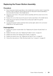
..."Replacing the Stand" on page 13. See "Replacing the System-Board Shield" on the system board. Postrequisites 1 Replace the system-board shield. Power-Button Assembly | 59 Ensure that the slot on the power-button assembly is secured under the tab on the middle frame. 2 Align the screw hole on the... and hard-drive activity light cable to the connector (PWRCN1) on page 36. 2 Replace the back cover. Replacing the Power-Button Assembly Procedure 1 Place the power-button assembly on page 20. 3 Replace the stand. See "Replacing the Back Cover" on the middle frame and then slide it toward ...
..."Replacing the Stand" on page 13. See "Replacing the System-Board Shield" on the system board. Postrequisites 1 Replace the system-board shield. Power-Button Assembly | 59 Ensure that the slot on the power-button assembly is secured under the tab on the middle frame. 2 Align the screw hole on the... and hard-drive activity light cable to the connector (PWRCN1) on page 36. 2 Replace the back cover. Replacing the Power-Button Assembly Procedure 1 Place the power-button assembly on page 20. 3 Replace the stand. See "Replacing the Back Cover" on the middle frame and then slide it toward ...

Specifications (SWF/PDF)
Page 60
60 | Power-Button Assembly
60 | Power-Button Assembly
Specifications (SWF/PDF)
Page 96
... the screen is a scrollable list containing features that option and available settings. This field appears on the right side of your computer, including installed hardware, power conservation, and security features. Press to make changes to highlight an option. NOTE: Not all settings listed in the Setup Item. Setup Item - As an...
... the screen is a scrollable list containing features that option and available settings. This field appears on the right side of your computer, including installed hardware, power conservation, and security features. Press to make changes to highlight an option. NOTE: Not all settings listed in the Setup Item. Setup Item - As an...
Specifications (SWF/PDF)
Page 102
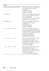
...LAN signals Enabled or Disabled (Disabled by default) Allows you to configure the behavior of your computer after it recovers from a power failure Power Off, Power On, or Last Power State (Power Off by default) Allows you to enable or disable the computer from turning on automatically Enabled or Disabled (Disabled by default) Allows... you to set the computer to turn on automatically; This option can be configured only if the Auto Power On mode is set to Enabled 1 to 31 (15 by default) Allows you to set the time at which the computer must turn on...
...LAN signals Enabled or Disabled (Disabled by default) Allows you to configure the behavior of your computer after it recovers from a power failure Power Off, Power On, or Last Power State (Power Off by default) Allows you to enable or disable the computer from turning on automatically Enabled or Disabled (Disabled by default) Allows... you to set the computer to turn on automatically; This option can be configured only if the Auto Power On mode is set to Enabled 1 to 31 (15 by default) Allows you to set the time at which the computer must turn on...


