Specifications (SWF/PDF)
Page 3
Contents 1 Technical Overview 7 Inside View of Your Computer 7 System Board Components 8 2 Before You Begin 11 Turn Off Your Computer and Connected Devices 11 Safety Instructions 11 Recommended Tools 12 3 After Working Inside Your Computer 13 4 Stand Cover 15 Removing the Stand ...
Contents 1 Technical Overview 7 Inside View of Your Computer 7 System Board Components 8 2 Before You Begin 11 Turn Off Your Computer and Connected Devices 11 Safety Instructions 11 Recommended Tools 12 3 After Working Inside Your Computer 13 4 Stand Cover 15 Removing the Stand ...
Specifications (SWF/PDF)
Page 11
... the computer. CAUTION: To avoid damaging the components and cards, handle them by touching an unpainted metal surface, such as the metal at dell.com/regulatory_compliance. Before You Begin | 11 NOTE: If you finish working inside the computer, replace all open programs. 2 Click Start and click... button for about safety precautions, working inside your computer. CAUTION: Only a certified service technician is flat and clean. 2 Before You Begin Turn Off Your Computer and Connected Devices CAUTION: To avoid losing data, save and close all open files and exit all covers, panels, and ...
... the computer. CAUTION: To avoid damaging the components and cards, handle them by touching an unpainted metal surface, such as the metal at dell.com/regulatory_compliance. Before You Begin | 11 NOTE: If you finish working inside the computer, replace all open programs. 2 Click Start and click... button for about safety precautions, working inside your computer. CAUTION: Only a certified service technician is flat and clean. 2 Before You Begin Turn Off Your Computer and Connected Devices CAUTION: To avoid losing data, save and close all open files and exit all covers, panels, and ...
Specifications (SWF/PDF)
Page 13
After Working Inside Your Computer | 13 Failure to their electrical outlets CAUTION: Before turning on your computer • Connect your computer and all screws and ensure that no stray screws remain inside your computer • Place the computer in ...
After Working Inside Your Computer | 13 Failure to their electrical outlets CAUTION: Before turning on your computer • Connect your computer and all screws and ensure that no stray screws remain inside your computer • Place the computer in ...
Specifications (SWF/PDF)
Page 27
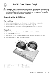
.... Procedure 1 Remove the screw that shipped with your computer, read the safety information that secures the B-CAS card to the middle frame. 2 Turn the B-CAS card over. 3 Disconnect the B-CAS-card cable from the connector on the B-CAS card. 4 Lift the B-CAS card away ... 3 screw 2 B-CAS card 4 B-CAS-card cable B-CAS Card (Japan Only) | 27 For additional safety best practices information, see the Regulatory Compliance Homepage at dell.com/regulatory_compliance. See "Removing the Stand" on page 15. 2 Remove the stand. See "Removing the Back Cover" on page 19. 9 B-CAS Card (Japan Only...
.... Procedure 1 Remove the screw that shipped with your computer, read the safety information that secures the B-CAS card to the middle frame. 2 Turn the B-CAS card over. 3 Disconnect the B-CAS-card cable from the connector on the B-CAS card. 4 Lift the B-CAS card away ... 3 screw 2 B-CAS card 4 B-CAS-card cable B-CAS Card (Japan Only) | 27 For additional safety best practices information, see the Regulatory Compliance Homepage at dell.com/regulatory_compliance. See "Removing the Stand" on page 15. 2 Remove the stand. See "Removing the Back Cover" on page 19. 9 B-CAS Card (Japan Only...
Specifications (SWF/PDF)
Page 28
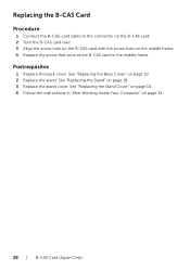
... secures the B-CAS card to the middle frame. Replacing the B-CAS Card Procedure 1 Connect the B-CAS-card cable to the connector on the B-CAS card. 2 Turn the B-CAS card over. 3 Align the screw hole on the B-CAS card with the screw hole on page 18. 3 Replace the stand cover. See "Replacing...
... secures the B-CAS card to the middle frame. Replacing the B-CAS Card Procedure 1 Connect the B-CAS-card cable to the connector on the B-CAS card. 2 Turn the B-CAS card over. 3 Align the screw hole on the B-CAS card with the screw hole on page 18. 3 Replace the stand cover. See "Replacing...
Specifications (SWF/PDF)
Page 35
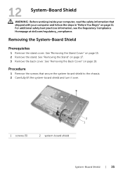
... Before working inside your computer, read the safety information that secure the system-board shield to the chassis. 2 Carefully lift the system-board shield and turn it over. 2 1 1 screws (5) 2 system-board shield System-Board Shield | 35 See "Removing the Back Cover" on page 15. 2... Remove the stand. For additional safety best practices information, see the Regulatory Compliance Homepage at dell.com/regulatory_compliance. See "Removing the Stand Cover" on page 19. Procedure 1 Remove the screws that shipped with your computer and follow the...
... Before working inside your computer, read the safety information that secure the system-board shield to the chassis. 2 Carefully lift the system-board shield and turn it over. 2 1 1 screws (5) 2 system-board shield System-Board Shield | 35 See "Removing the Back Cover" on page 15. 2... Remove the stand. For additional safety best practices information, see the Regulatory Compliance Homepage at dell.com/regulatory_compliance. See "Removing the Stand Cover" on page 19. Procedure 1 Remove the screws that shipped with your computer and follow the...
Specifications (SWF/PDF)
Page 36
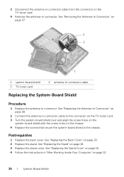
... cover. See "Replacing the Stand" on the chassis. 4 Replace the screws that secure the system-board shield to the connector on the TV-tuner card. 3 Turn the system-board shield over and align the screw holes on the system-board shield with the screw holes on page 18. 3 Replace the stand...
... cover. See "Replacing the Stand" on the chassis. 4 Replace the screws that secure the system-board shield to the connector on the TV-tuner card. 3 Turn the system-board shield over and align the screw holes on the system-board shield with the screw holes on page 18. 3 Replace the stand...
Specifications (SWF/PDF)
Page 71
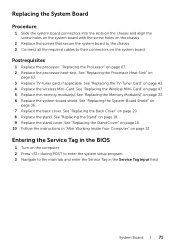
..." on page 20. 8 Replace the stand. Postrequisites 1 Replace the processor. See "Replacing the Stand Cover" on page 16. 10 Follow the instructions in the BIOS 1 Turn on page 63. 3 Replace TV-tuner card, if applicable. See "Replacing the Back Cover" on page 13. Replacing the System Board Procedure 1 Slide the system...
..." on page 20. 8 Replace the stand. Postrequisites 1 Replace the processor. See "Replacing the Stand Cover" on page 16. 10 Follow the instructions in the BIOS 1 Turn on page 63. 3 Replace TV-tuner card, if applicable. See "Replacing the Back Cover" on page 13. Replacing the System Board Procedure 1 Slide the system...
Specifications (SWF/PDF)
Page 95
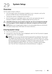
...desktop. NOTE: Before you change the settings for this keystroke is lost. This prompt can make your computer and try again. Then, turn off your computer work incorrectly. System Setup | 95 NOTE: The F2 prompt indicates that you write down the system setup screen information... information about the hardware installed on your computer. 2 During POST, when the DELL logo is recommended that the keyboard has initialized. See "Turn Off Your Computer and Connected Devices" on page 11. Entering System Setup 1 Turn on (or restart) your computer, such as the amount of RAM, the ...
...desktop. NOTE: Before you change the settings for this keystroke is lost. This prompt can make your computer and try again. Then, turn off your computer work incorrectly. System Setup | 95 NOTE: The F2 prompt indicates that you write down the system setup screen information... information about the hardware installed on your computer. 2 During POST, when the DELL logo is recommended that the keyboard has initialized. See "Turn Off Your Computer and Connected Devices" on page 11. Entering System Setup 1 Turn on (or restart) your computer, such as the amount of RAM, the ...
Specifications (SWF/PDF)
Page 102
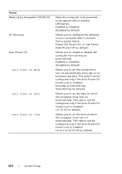
... On, or Last Power State (Power Off by default) Allows you to enable or disable the computer from turning on automatically Enabled or Disabled (Disabled by default) Allows you to set the computer to turn on automatically every day or on a preselected date; This option can be configured only if the Auto... On mode is set to Enabled Everyday or Selected Day (Selected Day by default) Allows you to set the date on which the computer must turn on automatically; Power Wake Up by Integrated LAN/WLAN AC Recovery Auto Power On Auto Power On Mode Auto Power On Date Auto Power On...
... On, or Last Power State (Power Off by default) Allows you to enable or disable the computer from turning on automatically Enabled or Disabled (Disabled by default) Allows you to set the computer to turn on automatically every day or on a preselected date; This option can be configured only if the Auto... On mode is set to Enabled Everyday or Selected Day (Selected Day by default) Allows you to set the date on which the computer must turn on automatically; Power Wake Up by Integrated LAN/WLAN AC Recovery Auto Power On Auto Power On Mode Auto Power On Date Auto Power On...
Specifications (SWF/PDF)
Page 105
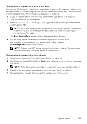
... until you are booting to restore it. 3 Press the up- NOTE: To boot to run Dell Diagnostics from . Changing Boot Sequence for example, to boot from a USB device, connect the USB device to a USB port. 2 Turn on page 95. 2 Use the arrow keys to highlight the Boot menu option and press to...
... until you are booting to restore it. 3 Press the up- NOTE: To boot to run Dell Diagnostics from . Changing Boot Sequence for example, to boot from a USB device, connect the USB device to a USB port. 2 Turn on page 95. 2 Use the arrow keys to highlight the Boot menu option and press to...
Specifications (SWF/PDF)
Page 109
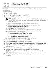
If you have your computer's Service Tag or Express Service Code: a Select one of the following options: • Automatically detect my Service Tag for your computer is located on a label at the back of results appears on the ... downloaded the BIOS update file. The file icon appears in the Service Tag or Express Service Code field. To flash the BIOS: 1 Turn on the computer. 2 Go to support.dell.com/support/downloads. 3 Locate the BIOS update file for your computer: NOTE: The Service Tag for me • Choose from My Products...
If you have your computer's Service Tag or Express Service Code: a Select one of the following options: • Automatically detect my Service Tag for your computer is located on a label at the back of results appears on the ... downloaded the BIOS update file. The file icon appears in the Service Tag or Express Service Code field. To flash the BIOS: 1 Turn on the computer. 2 Go to support.dell.com/support/downloads. 3 Locate the BIOS update file for your computer: NOTE: The Service Tag for me • Choose from My Products...


