Specifications (SWF/PDF)
Page 3
... 11 Turn Off Your Computer and Connected Devices 11 Safety Instructions 11 Recommended Tools 12 3 After Working Inside Your Computer 13 4 Stand Cover 15 Removing the Stand Cover 15 Replacing the Stand Cover 16 5 Stand 17 Removing the Stand 17 Replacing the Stand 18 6 Back Cover 19 Removing the Back Cover 19 Replacing the Back Cover 20 7 Hard Drive 21 Removing the Hard Drive 21 Replacing the Hard Drive 23 8 Optical Drive 25 Removing the Optical Drive 25 Replacing the Optical Drive 26 9 B-CAS Card...
... 11 Turn Off Your Computer and Connected Devices 11 Safety Instructions 11 Recommended Tools 12 3 After Working Inside Your Computer 13 4 Stand Cover 15 Removing the Stand Cover 15 Replacing the Stand Cover 16 5 Stand 17 Removing the Stand 17 Replacing the Stand 18 6 Back Cover 19 Removing the Back Cover 19 Replacing the Back Cover 20 7 Hard Drive 21 Removing the Hard Drive 21 Replacing the Hard Drive 23 8 Optical Drive 25 Removing the Optical Drive 25 Replacing the Optical Drive 26 9 B-CAS Card...
Specifications (SWF/PDF)
Page 9
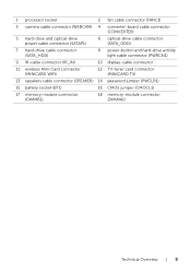
1 processor socket 2 fan cable connector (FANC1) 3 camera cable connector (WEBCAM) 4 converter-board cable connector (CONVERTER) 5 hard-drive and optical-drive power cable connector (SATAP1) 6 optical-drive cable connector (SATA_ODD) 7 hard-drive cable connector (SATA_HDD) 8 power-button and hard-drive activity light cable connector (PWRCN1) 9 IR-cable connector (IR_IN) 10 display-cable connector 11 wireless Mini-Card connector (MINICARD WIFI) 12 TV-tuner card connector (MINICARD TV) 13 speakers cable connector (SPEAKER) 14 password jumper (PWCLR1) 15 battery socket (BT1) 16 CMOS ...
1 processor socket 2 fan cable connector (FANC1) 3 camera cable connector (WEBCAM) 4 converter-board cable connector (CONVERTER) 5 hard-drive and optical-drive power cable connector (SATAP1) 6 optical-drive cable connector (SATA_ODD) 7 hard-drive cable connector (SATA_HDD) 8 power-button and hard-drive activity light cable connector (PWRCN1) 9 IR-cable connector (IR_IN) 10 display-cable connector 11 wireless Mini-Card connector (MINICARD WIFI) 12 TV-tuner card connector (MINICARD TV) 13 speakers cable connector (SPEAKER) 14 password jumper (PWCLR1) 15 battery socket (BT1) 16 CMOS ...
Specifications (SWF/PDF)
Page 11
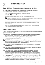
... touching pins and contacts. After you finish working inside your computer. CAUTION: Only a certified service technician is flat and clean. WARNING: Before working inside the computer, replace all covers, panels, and screws before connecting to ground the system board. Microsoft Windows shuts down . CAUTION: To avoid damaging the components and cards, handle them by their electrical outlets. 4 Disconnect all telephone cables, network cables, and attached devices from...
... touching pins and contacts. After you finish working inside your computer. CAUTION: Only a certified service technician is flat and clean. WARNING: Before working inside the computer, replace all covers, panels, and screws before connecting to ground the system board. Microsoft Windows shuts down . CAUTION: To avoid damaging the components and cards, handle them by their electrical outlets. 4 Disconnect all telephone cables, network cables, and attached devices from...
Specifications (SWF/PDF)
Page 12
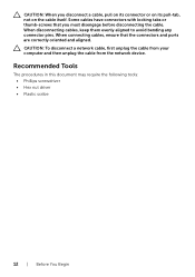
... disconnect a network cable, first unplug the cable from your computer and then unplug the cable from the network device. When connecting cables, ensure that you disconnect a cable, pull on its connector or on its pull-tab, not on the cable itself. CAUTION: When you must disengage before disconnecting the cable. Some cables have connectors with locking tabs or thumb-screws that the connectors and ports are...
... disconnect a network cable, first unplug the cable from your computer and then unplug the cable from the network device. When connecting cables, ensure that you disconnect a cable, pull on its connector or on its pull-tab, not on the cable itself. CAUTION: When you must disengage before disconnecting the cable. Some cables have connectors with locking tabs or thumb-screws that the connectors and ports are...
Specifications (SWF/PDF)
Page 13
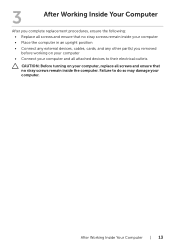
After Working Inside Your Computer | 13 Failure to their electrical outlets CAUTION: Before turning on your computer, replace all attached devices to do so may damage your computer and all screws and ensure that no stray screws remain inside your computer • Place the computer in an upright position • Connect any external devices, cables, cards, and any other part(s) you removed before working on your...
After Working Inside Your Computer | 13 Failure to their electrical outlets CAUTION: Before turning on your computer, replace all attached devices to do so may damage your computer and all screws and ensure that no stray screws remain inside your computer • Place the computer in an upright position • Connect any external devices, cables, cards, and any other part(s) you removed before working on your...
Specifications (SWF/PDF)
Page 23
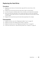
.... 3 Replace the stand cover. Ensure that the slots on the hard-drive cage are secured under the tabs on the chassis. 5 Replace the screws that secure the hard-drive cage to the hard drive. 3 Connect the power and data cable to the chassis. Postrequisites 1 Replace the back cover. See "Replacing the Stand Cover" on page 16. 4 Follow the instructions in "After Working Inside Your Computer" on page 13. Replacing the Hard Drive Procedure...
.... 3 Replace the stand cover. Ensure that the slots on the hard-drive cage are secured under the tabs on the chassis. 5 Replace the screws that secure the hard-drive cage to the hard drive. 3 Connect the power and data cable to the chassis. Postrequisites 1 Replace the back cover. See "Replacing the Stand Cover" on page 16. 4 Follow the instructions in "After Working Inside Your Computer" on page 13. Replacing the Hard Drive Procedure...
Specifications (SWF/PDF)
Page 26
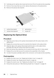
.... 4 Follow the instructions in "After Working Inside Your Computer" on page 20. 2 Replace the stand. See "Replacing the Back Cover" on page 13. 26 | Optical Drive 4 Carefully pry the optical-drive bezel and remove it from the optical-drive assembly. 5 Remove the screws that secure the optical-drive bracket to the optical drive. 6 Remove the optical-drive bracket. 4 3 1 2 1 optical-drive bezel 3 optical-drive bracket 2 optical drive 4 screws (2) Replacing the Optical Drive Procedure 1 Align the screw holes on the optical-drive bracket with...
.... 4 Follow the instructions in "After Working Inside Your Computer" on page 20. 2 Replace the stand. See "Replacing the Back Cover" on page 13. 26 | Optical Drive 4 Carefully pry the optical-drive bezel and remove it from the optical-drive assembly. 5 Remove the screws that secure the optical-drive bracket to the optical drive. 6 Remove the optical-drive bracket. 4 3 1 2 1 optical-drive bezel 3 optical-drive bracket 2 optical drive 4 screws (2) Replacing the Optical Drive Procedure 1 Align the screw holes on the optical-drive bracket with...
Specifications (SWF/PDF)
Page 33
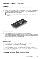
... clicks into the slots on the system-board shield and then slide the memory-module shield toward the bottom of memory installed on page 13. To confirm the amount of the computer. Postrequisites 1 Replace the back cover. See "Replacing the Stand Cover" on page 16. 4 Follow the instructions in "After Working Inside Your Computer" on your computer: Click Start → Control Panel→ System and...
... clicks into the slots on the system-board shield and then slide the memory-module shield toward the bottom of memory installed on page 13. To confirm the amount of the computer. Postrequisites 1 Replace the back cover. See "Replacing the Stand Cover" on page 16. 4 Follow the instructions in "After Working Inside Your Computer" on your computer: Click Start → Control Panel→ System and...
Specifications (SWF/PDF)
Page 59
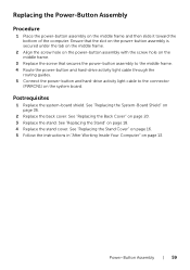
... the power-button assembly with the screw hole on the middle frame. 3 Replace the screw that secures the power-button assembly to the middle frame. 4 Route the power-button and hard-drive activity light cable through the routing guides. 5 Connect the power-button and hard-drive activity light cable to the connector (PWRCN1) on page 36. 2 Replace the back cover. Power-Button Assembly | 59 See "Replacing the System-Board Shield" on the system board. Postrequisites 1 Replace the system-board...
... the power-button assembly with the screw hole on the middle frame. 3 Replace the screw that secures the power-button assembly to the middle frame. 4 Route the power-button and hard-drive activity light cable through the routing guides. 5 Connect the power-button and hard-drive activity light cable to the connector (PWRCN1) on page 36. 2 Replace the back cover. Power-Button Assembly | 59 See "Replacing the System-Board Shield" on the system board. Postrequisites 1 Replace the system-board...
Specifications (SWF/PDF)
Page 71
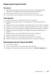
... card, if applicable. See "Replacing the Processor Heat-Sink" on page 20. 8 Replace the stand. Entering the Service Tag in the BIOS 1 Turn on the computer. 2 Press during POST to enter the system setup program. 3 Navigate to their connectors on page 16. 10 Follow the instructions in the Service Tag Input field. See "Replacing the Memory Module(s)" on page 36. 7 Replace the back cover. See "Replacing the System-Board...
... card, if applicable. See "Replacing the Processor Heat-Sink" on page 20. 8 Replace the stand. Entering the Service Tag in the BIOS 1 Turn on the computer. 2 Press during POST to enter the system setup program. 3 Navigate to their connectors on page 16. 10 Follow the instructions in the Service Tag Input field. See "Replacing the Memory Module(s)" on page 36. 7 Replace the back cover. See "Replacing the System-Board...
Specifications (SWF/PDF)
Page 77
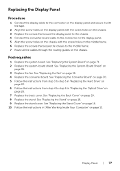
... instructions from step 3 to step 5 in "Replacing the Hard Drive" on page 23. 6 Follow the instructions from step 4 to the middle frame. 7 Route all the cables through the routing guides on page 71. 2 Replace the system-board shield. See "Replacing the Stand" on page 26. 7 Replace the back cover. See "Replacing the System Board" on the chassis. Replacing the Display Panel Procedure 1 Connect the display cable to the connector on the display panel...
... instructions from step 3 to step 5 in "Replacing the Hard Drive" on page 23. 6 Follow the instructions from step 4 to the middle frame. 7 Route all the cables through the routing guides on page 71. 2 Replace the system-board shield. See "Replacing the Stand" on page 26. 7 Replace the back cover. See "Replacing the System Board" on the chassis. Replacing the Display Panel Procedure 1 Connect the display cable to the connector on the display panel...
Specifications (SWF/PDF)
Page 82
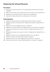
... "Replacing the Converter Board" on page 30. 5 Follow the instructions from step 3 to step 5 in "Replacing the Hard Drive" on page 23. 6 Follow the instructions from step 4 to the middle frame. 4 Route all the cables through the routing guides on the chassis. See "Replacing the Stand Cover" on page 16. 10 Follow the instructions in "Replacing the Optical Drive" on page 26. 7 Replace the back cover. See "Replacing...
... "Replacing the Converter Board" on page 30. 5 Follow the instructions from step 3 to step 5 in "Replacing the Hard Drive" on page 23. 6 Follow the instructions from step 4 to the middle frame. 4 Route all the cables through the routing guides on the chassis. See "Replacing the Stand Cover" on page 16. 10 Follow the instructions in "Replacing the Optical Drive" on page 26. 7 Replace the back cover. See "Replacing...
Specifications (SWF/PDF)
Page 85
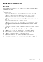
... "Replacing the Display Panel" on page 18. 13 Replace the stand cover. See "Replacing the Stand" on page 77. 3 Replace the system board. See "Replacing the Converter Board" on page 30. 7 Follow the instructions from step 3 to step 5 in "Replacing the Hard Drive" on page 23. 8 Follow the instructions from step 4 to step 6 in "After Working Inside Your Computer" on page 53. 10 Replace the B-CAS card. See "Replacing the Fan...
... "Replacing the Display Panel" on page 18. 13 Replace the stand cover. See "Replacing the Stand" on page 77. 3 Replace the system board. See "Replacing the Converter Board" on page 30. 7 Follow the instructions from step 3 to step 5 in "Replacing the Hard Drive" on page 23. 8 Follow the instructions from step 4 to step 6 in "After Working Inside Your Computer" on page 53. 10 Replace the B-CAS card. See "Replacing the Fan...
Specifications (SWF/PDF)
Page 95
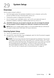
... System Setup Overview Use the system setup to utility to: • Get information about the hardware installed on your computer, such as the amount of RAM, the size of the hard drive, and so on • Change the system configuration information • Set or change a user-selectable option, such as the user password, type of hard drive installed, enabling or disabling base devices, and so on (or restart) your computer. 2 During POST, when the DELL...
... System Setup Overview Use the system setup to utility to: • Get information about the hardware installed on your computer, such as the amount of RAM, the size of the hard drive, and so on • Change the system configuration information • Set or change a user-selectable option, such as the user password, type of hard drive installed, enabling or disabling base devices, and so on (or restart) your computer. 2 During POST, when the DELL...

Specifications (SWF/PDF)
Page 97
... Service Tag Service Tag Input Asset Tag Displays the BIOS revision number Displays the BIOS build date in mm/dd/yyyy format Displays the computer model Displays the current time in hh:mm:ss format Displays the current date in MHz Indicates the type of installed memory System Setup | 97 Memory Information Memory Installed Memory Running Speed Memory Technology Indicates the amount of memory installed in MB Indicates the memory speed in mm/dd/yyyy format Displays...
... Service Tag Service Tag Input Asset Tag Displays the BIOS revision number Displays the BIOS build date in mm/dd/yyyy format Displays the computer model Displays the current time in hh:mm:ss format Displays the current date in MHz Indicates the type of installed memory System Setup | 97 Memory Information Memory Installed Memory Running Speed Memory Technology Indicates the amount of memory installed in MB Indicates the memory speed in mm/dd/yyyy format Displays...
Specifications (SWF/PDF)
Page 98
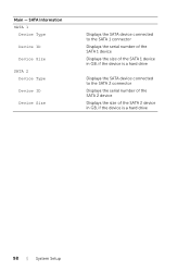
Main - SATA Information SATA 1 Device Type Device ID Device Size SATA 2 Device Type Device ID Device Size Displays the SATA device connected to the SATA 1 connector Displays the serial number of the SATA 1 device Displays the size of the SATA 1 device in GB, if the device is a hard drive Displays the SATA device connected to the SATA 2 connector Displays the serial number of the SATA 2 device Displays the size of the SATA 2 device in GB, if the device is a hard drive 98 | System Setup
Main - SATA Information SATA 1 Device Type Device ID Device Size SATA 2 Device Type Device ID Device Size Displays the SATA device connected to the SATA 1 connector Displays the serial number of the SATA 1 device Displays the size of the SATA 1 device in GB, if the device is a hard drive Displays the SATA device connected to the SATA 2 connector Displays the serial number of the SATA 2 device Displays the size of the SATA 2 device in GB, if the device is a hard drive 98 | System Setup
Specifications (SWF/PDF)
Page 101
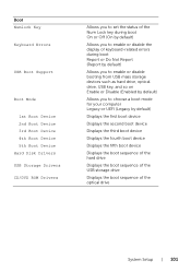
... Key Keyboard Errors USB Boot Support Boot Mode 1st Boot Device 2nd Boot Device 3rd Boot Device 4th Boot Device 5th Boot Device Hard Disk Drivers USB Storage Drivers CD/DVD ROM Drivers Allows you to set the status of the Num Lock key during boot On or Off (On by default) Allows you to enable or disable the display of keyboard-related errors during boot Report or Do Not Report (Report by default) Allows you to enable or disable booting from USB mass storage devices such as hard drive, optical drive, USB key, and so on Enable or Disable (Enabled...
... Key Keyboard Errors USB Boot Support Boot Mode 1st Boot Device 2nd Boot Device 3rd Boot Device 4th Boot Device 5th Boot Device Hard Disk Drivers USB Storage Drivers CD/DVD ROM Drivers Allows you to set the status of the Num Lock key during boot On or Off (On by default) Allows you to enable or disable the display of keyboard-related errors during boot Report or Do Not Report (Report by default) Allows you to enable or disable booting from USB mass storage devices such as hard drive, optical drive, USB key, and so on Enable or Disable (Enabled...
Specifications (SWF/PDF)
Page 102
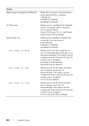
... must turn on automatically; Power Wake Up by Integrated LAN/WLAN AC Recovery Auto Power On Auto Power On Mode Auto Power On Date Auto Power On Time Allow the computer to be powered on by special LAN or wireless LAN signals Enabled or Disabled (Disabled by default) Allows you to configure the behavior of your computer after it recovers from a power failure Power Off, Power On, or Last Power State (Power Off by default) Allows...
... must turn on automatically; Power Wake Up by Integrated LAN/WLAN AC Recovery Auto Power On Auto Power On Mode Auto Power On Date Auto Power On Time Allow the computer to be powered on by special LAN or wireless LAN signals Enabled or Disabled (Disabled by default) Allows you to configure the behavior of your computer after it recovers from a power failure Power Off, Power On, or Last Power State (Power Off by default) Allows...
Specifications (SWF/PDF)
Page 104
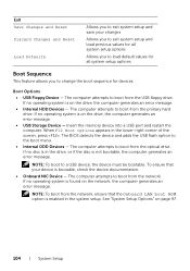
... your device is enabled in the system setup. Exit Save Changes and Reset Discard Changes and Reset Load Defaults Allows you to change the boot sequence for devices. The computer attempts to boot from the primary hard drive. The computer attempts to boot from the optical drive. The computer attempts to boot from the USB floppy drive. The computer attempts to boot from the network. The BIOS detects the device and adds the USB flash option to a USB device, the device...
... your device is enabled in the system setup. Exit Save Changes and Reset Discard Changes and Reset Load Defaults Allows you to change the boot sequence for devices. The computer attempts to boot from the primary hard drive. The computer attempts to boot from the optical drive. The computer attempts to boot from the USB floppy drive. The computer attempts to boot from the network. The BIOS detects the device and adds the USB flash option to a USB device, the device...
Specifications (SWF/PDF)
Page 105
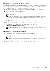
... the optical drive to run Dell Diagnostics from a USB device, connect the USB device to change the boot priority of the device. See "Entering System Setup" on (or restart) your current boot sequence in the lower-right corner of the screen, press . NOTE: Write down -arrow keys to move through the list of devices. 4 Press plus (+) or minus (-) to a USB port. 2 Turn on page 95. 2 Use the arrow keys to highlight the Boot menu option and press to restore...
... the optical drive to run Dell Diagnostics from a USB device, connect the USB device to change the boot priority of the device. See "Entering System Setup" on (or restart) your current boot sequence in the lower-right corner of the screen, press . NOTE: Write down -arrow keys to move through the list of devices. 4 Press plus (+) or minus (-) to a USB port. 2 Turn on page 95. 2 Use the arrow keys to highlight the Boot menu option and press to restore...


