Specifications (SWF/PDF)
Page 2
...death. Microsoft®, Windows®, and the Windows start button logo are trademarks of Dell Inc.; Other trademarks and trade names may be used in this text: Dell™, the DELL logo, and Inspiron™ are either the entities claiming the marks and names or their products. is... a registered trademark owned by Dell under license. Trademarks used by Bluetooth SIG, Inc. Dell Inc. Intel® and Intel SpeedStep...
...death. Microsoft®, Windows®, and the Windows start button logo are trademarks of Dell Inc.; Other trademarks and trade names may be used in this text: Dell™, the DELL logo, and Inspiron™ are either the entities claiming the marks and names or their products. is... a registered trademark owned by Dell under license. Trademarks used by Bluetooth SIG, Inc. Dell Inc. Intel® and Intel SpeedStep...
Specifications (SWF/PDF)
Page 3
Contents 1 Technical Overview 7 Inside View of Your Computer 7 System Board Components 8 2 Before You Begin 11 Turn Off Your Computer and Connected Devices 11 Safety Instructions 11 Recommended Tools 12 3 After Working Inside Your Computer 13 4 Stand Cover 15 Removing the Stand Cover 15 Replacing the Stand Cover 16 5 Stand 17 Removing the Stand 17 Replacing the Stand 18 6 Back Cover 19 Removing the Back Cover 19 Replacing the Back Cover 20 7 Hard Drive 21 Removing the Hard Drive 21 Replacing the Hard Drive 23 8 Optical Drive 25 Removing the Optical Drive 25 Replacing the...
Contents 1 Technical Overview 7 Inside View of Your Computer 7 System Board Components 8 2 Before You Begin 11 Turn Off Your Computer and Connected Devices 11 Safety Instructions 11 Recommended Tools 12 3 After Working Inside Your Computer 13 4 Stand Cover 15 Removing the Stand Cover 15 Replacing the Stand Cover 16 5 Stand 17 Removing the Stand 17 Replacing the Stand 18 6 Back Cover 19 Removing the Back Cover 19 Replacing the Back Cover 20 7 Hard Drive 21 Removing the Hard Drive 21 Replacing the Hard Drive 23 8 Optical Drive 25 Removing the Optical Drive 25 Replacing the...

Specifications (SWF/PDF)
Page 4
10 Converter Board 29 Removing the Converter Board 29 Replacing the Converter Board 30 11 Memory Module(s 31 Removing the Memory Module(s 31 Replacing the Memory Module(s 33 12 System-Board Shield 35 Removing the System-Board Shield 35 Replacing the System-Board Shield 36 13 Antenna-In Connector 37 Removing the Antenna-In Connector 37 Replacing the Antenna-In Connector 38 14 Antenna Modules 39 Removing the Antenna Modules 39 Replacing the Antenna Modules 40 15 TV-Tuner Card (Optional 41 Removing the TV-Tuner Card 41 Replacing the TV-Tuner Card 43 16 Wireless Mini-Card (...
10 Converter Board 29 Removing the Converter Board 29 Replacing the Converter Board 30 11 Memory Module(s 31 Removing the Memory Module(s 31 Replacing the Memory Module(s 33 12 System-Board Shield 35 Removing the System-Board Shield 35 Replacing the System-Board Shield 36 13 Antenna-In Connector 37 Removing the Antenna-In Connector 37 Replacing the Antenna-In Connector 38 14 Antenna Modules 39 Removing the Antenna Modules 39 Replacing the Antenna Modules 40 15 TV-Tuner Card (Optional 41 Removing the TV-Tuner Card 41 Replacing the TV-Tuner Card 43 16 Wireless Mini-Card (...
Specifications (SWF/PDF)
Page 5
20 Power-Button Assembly 57 Removing the Power-Button Assembly 57 Replacing the Power-Button Assembly 59 21 Processor Heat-Sink 61 Removing the Processor Heat-Sink 61 Replacing the Processor Heat-Sink 63 22 Processor 65 Removing the Processor 65 Replacing the Processor 67 23 System Board 69 Removing the System Board 69 Replacing the System Board 71 Entering the Service Tag in the BIOS 71 24 Display Panel 73 Removing the Display Panel 73 Replacing the Display Panel 77 25 Infrared (IR) Receiver 79 Removing the Infrared Receiver 79 Replacing the Infrared Receiver 82 26 Middle ...
20 Power-Button Assembly 57 Removing the Power-Button Assembly 57 Replacing the Power-Button Assembly 59 21 Processor Heat-Sink 61 Removing the Processor Heat-Sink 61 Replacing the Processor Heat-Sink 63 22 Processor 65 Removing the Processor 65 Replacing the Processor 67 23 System Board 69 Removing the System Board 69 Replacing the System Board 71 Entering the Service Tag in the BIOS 71 24 Display Panel 73 Removing the Display Panel 73 Replacing the Display Panel 77 25 Infrared (IR) Receiver 79 Removing the Infrared Receiver 79 Replacing the Infrared Receiver 82 26 Middle ...
Specifications (SWF/PDF)
Page 6
29 System Setup 95 Overview 95 Clearing Forgotten Passwords 106 Clearing CMOS Settings 107 30 Flashing the BIOS 109 6 | Contents
29 System Setup 95 Overview 95 Clearing Forgotten Passwords 106 Clearing CMOS Settings 107 30 Flashing the BIOS 109 6 | Contents
Specifications (SWF/PDF)
Page 7
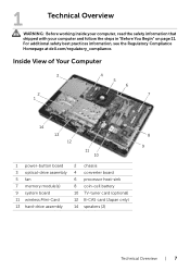
... TV-tuner card (optional) 12 B-CAS card (Japan only) 14 speakers (2) Technical Overview | 7 For additional safety best practices information, see the Regulatory Compliance Homepage at dell.com/regulatory_compliance. 1 Technical Overview WARNING: Before working inside your computer, read the safety information that shipped with your computer and follow the steps in "Before...
... TV-tuner card (optional) 12 B-CAS card (Japan only) 14 speakers (2) Technical Overview | 7 For additional safety best practices information, see the Regulatory Compliance Homepage at dell.com/regulatory_compliance. 1 Technical Overview WARNING: Before working inside your computer, read the safety information that shipped with your computer and follow the steps in "Before...
Specifications (SWF/PDF)
Page 9
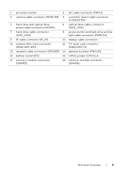
1 processor socket 2 fan cable connector (FANC1) 3 camera cable connector (WEBCAM) 4 converter-board cable connector (CONVERTER) 5 hard-drive and optical-drive power cable connector (SATAP1) 6 optical-drive cable connector (SATA_ODD) 7 hard-drive cable connector (SATA_HDD) 8 power-button and hard-drive activity light cable connector (PWRCN1) 9 IR-cable connector (IR_IN) 10 display-cable connector 11 wireless Mini-Card connector (MINICARD WIFI) 12 TV-tuner card connector (MINICARD TV) 13 speakers cable connector (SPEAKER) 14 password jumper (PWCLR1) 15 battery socket (BT1) 16 CMOS ...
1 processor socket 2 fan cable connector (FANC1) 3 camera cable connector (WEBCAM) 4 converter-board cable connector (CONVERTER) 5 hard-drive and optical-drive power cable connector (SATAP1) 6 optical-drive cable connector (SATA_ODD) 7 hard-drive cable connector (SATA_HDD) 8 power-button and hard-drive activity light cable connector (PWRCN1) 9 IR-cable connector (IR_IN) 10 display-cable connector 11 wireless Mini-Card connector (MINICARD WIFI) 12 TV-tuner card connector (MINICARD TV) 13 speakers cable connector (SPEAKER) 14 password jumper (PWCLR1) 15 battery socket (BT1) 16 CMOS ...
Specifications (SWF/PDF)
Page 11
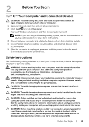
... off your personal safety. CAUTION: To avoid damaging the components and cards, handle them by touching an unpainted metal surface, such as the metal at dell.com/regulatory_compliance. Before You Begin | 11
... off your personal safety. CAUTION: To avoid damaging the components and cards, handle them by touching an unpainted metal surface, such as the metal at dell.com/regulatory_compliance. Before You Begin | 11
Specifications (SWF/PDF)
Page 12
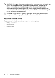
When disconnecting cables, keep them evenly aligned to avoid bending any connector pins. When connecting cables, ensure that you disconnect a cable, pull on its connector or on its pull-tab, not on the cable itself. Some cables have connectors with locking tabs or thumb-screws that the connectors and ports are correctly oriented and aligned. CAUTION: When you must disengage before disconnecting the cable. Recommended Tools The procedures in this document may require the following tools: • Phillips screwdriver • Hex nut driver • Plastic scribe 12 | Before You ...
When disconnecting cables, keep them evenly aligned to avoid bending any connector pins. When connecting cables, ensure that you disconnect a cable, pull on its connector or on its pull-tab, not on the cable itself. Some cables have connectors with locking tabs or thumb-screws that the connectors and ports are correctly oriented and aligned. CAUTION: When you must disengage before disconnecting the cable. Recommended Tools The procedures in this document may require the following tools: • Phillips screwdriver • Hex nut driver • Plastic scribe 12 | Before You ...
Specifications (SWF/PDF)
Page 13
Failure to do so may damage your computer, replace all attached devices to their electrical outlets CAUTION: Before turning on your computer. After Working Inside Your Computer | 13 3 After Working Inside Your Computer After you complete replacement procedures, ensure the following: • Replace all screws and ensure that no stray screws remain inside your computer • Place the computer in an upright position • Connect any external devices, cables, cards, and any other part(s) you removed before working on your computer • Connect your computer and all screws and ...
Failure to do so may damage your computer, replace all attached devices to their electrical outlets CAUTION: Before turning on your computer. After Working Inside Your Computer | 13 3 After Working Inside Your Computer After you complete replacement procedures, ensure the following: • Replace all screws and ensure that no stray screws remain inside your computer • Place the computer in an upright position • Connect any external devices, cables, cards, and any other part(s) you removed before working on your computer • Connect your computer and all screws and ...
Specifications (SWF/PDF)
Page 15
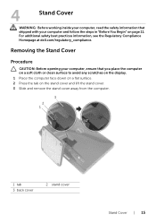
... the computer face down on a flat surface. 2 Press the tab on page 11. For additional safety best practices information, see the Regulatory Compliance Homepage at dell.com/regulatory_compliance.
... the computer face down on a flat surface. 2 Press the tab on page 11. For additional safety best practices information, see the Regulatory Compliance Homepage at dell.com/regulatory_compliance.

Specifications (SWF/PDF)
Page 16
Replacing the Stand Cover Procedure 1 Slide the tabs on the stand cover into the slots on the back cover. 2 Snap the stand cover until it clicks into place. 3 Follow the instructions in "After Working Inside Your Computer" on page 13. 16 | Stand Cover
Replacing the Stand Cover Procedure 1 Slide the tabs on the stand cover into the slots on the back cover. 2 Snap the stand cover until it clicks into place. 3 Follow the instructions in "After Working Inside Your Computer" on page 13. 16 | Stand Cover
Specifications (SWF/PDF)
Page 17
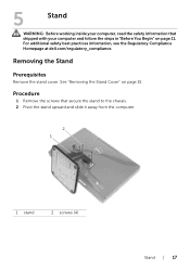
Removing the Stand Prerequisites Remove the stand cover. See "Removing the Stand Cover" on page 11. Procedure 1 Remove the screws that shipped with your computer and follow the steps in "Before You Begin" on page 15. For additional safety best practices information, see the Regulatory Compliance Homepage at dell.com/regulatory_compliance. 5 Stand WARNING: Before working inside your computer, read the safety information that secure the stand to the chassis. 2 Pivot the stand upward and slide it away from the computer. 2 1 1 stand 2 screws (4) Stand | 17
Removing the Stand Prerequisites Remove the stand cover. See "Removing the Stand Cover" on page 11. Procedure 1 Remove the screws that shipped with your computer and follow the steps in "Before You Begin" on page 15. For additional safety best practices information, see the Regulatory Compliance Homepage at dell.com/regulatory_compliance. 5 Stand WARNING: Before working inside your computer, read the safety information that secure the stand to the chassis. 2 Pivot the stand upward and slide it away from the computer. 2 1 1 stand 2 screws (4) Stand | 17

Specifications (SWF/PDF)
Page 18
Postrequisites 1 Replace the stand cover. See "Replacing the Stand Cover" on page 16. 2 Follow the instructions in "After Working Inside Your Computer" on the back cover. 2 Replace the screws that secure the stand to the chassis. Replacing the Stand Procedure 1 Slide the tabs on the stand into the slots on page 13. 18 | Stand
Postrequisites 1 Replace the stand cover. See "Replacing the Stand Cover" on page 16. 2 Follow the instructions in "After Working Inside Your Computer" on the back cover. 2 Replace the screws that secure the stand to the chassis. Replacing the Stand Procedure 1 Slide the tabs on the stand into the slots on page 13. 18 | Stand
Specifications (SWF/PDF)
Page 19
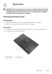
For additional safety best practices information, see the Regulatory Compliance Homepage at dell.com/regulatory_compliance. Procedure 1 Starting from above the optical drive, pry the back cover from the middle frame. 2 Lift the back cover off the computer. 1 2 1 middle ...
For additional safety best practices information, see the Regulatory Compliance Homepage at dell.com/regulatory_compliance. Procedure 1 Starting from above the optical drive, pry the back cover from the middle frame. 2 Lift the back cover off the computer. 1 2 1 middle ...

Specifications (SWF/PDF)
Page 20
Replacing the Back Cover Procedure Align the tabs on the back cover with the tabs on page 18. 2 Replace the stand cover. See "Replacing the Stand" on the middle frame and snap the back cover into place. Postrequisites 1 Replace the stand. See "Replacing the Stand Cover" on page 16. 3 Follow the instructions in "After Working Inside Your Computer" on page 13. 20 | Back Cover
Replacing the Back Cover Procedure Align the tabs on the back cover with the tabs on page 18. 2 Replace the stand cover. See "Replacing the Stand" on the middle frame and snap the back cover into place. Postrequisites 1 Replace the stand. See "Replacing the Stand Cover" on page 16. 3 Follow the instructions in "After Working Inside Your Computer" on page 13. 20 | Back Cover
Specifications (SWF/PDF)
Page 21
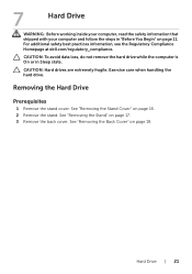
... while the computer is On or in "Before You Begin" on page 19. For additional safety best practices information, see the Regulatory Compliance Homepage at dell.com/regulatory_compliance. Exercise care when handling the hard drive. Hard Drive | 21 See "Removing the Back Cover" on page 11. Removing the Hard Drive Prerequisites...
... while the computer is On or in "Before You Begin" on page 19. For additional safety best practices information, see the Regulatory Compliance Homepage at dell.com/regulatory_compliance. Exercise care when handling the hard drive. Hard Drive | 21 See "Removing the Back Cover" on page 11. Removing the Hard Drive Prerequisites...

Specifications (SWF/PDF)
Page 22
Procedure 1 Remove the screws that secure the hard-drive assembly to the chassis. 2 Slide and lift the hard-drive assembly and then disconnect the power and data cable from the connector on the hard drive. 2 3 4 1 1 chassis 3 hard-drive assembly 2 screw (3) 4 power and data cable 3 Remove the screws that secure the hard-drive cage to the hard drive. 4 Lift the hard-drive cage off the hard drive. 1 hard-drive cage 3 screws (4) 1 23 2 hard drive 22 | Hard Drive
Procedure 1 Remove the screws that secure the hard-drive assembly to the chassis. 2 Slide and lift the hard-drive assembly and then disconnect the power and data cable from the connector on the hard drive. 2 3 4 1 1 chassis 3 hard-drive assembly 2 screw (3) 4 power and data cable 3 Remove the screws that secure the hard-drive cage to the hard drive. 4 Lift the hard-drive cage off the hard drive. 1 hard-drive cage 3 screws (4) 1 23 2 hard drive 22 | Hard Drive
Specifications (SWF/PDF)
Page 23
See "Replacing the Back Cover" on page 13. Ensure that the slots on the hard-drive cage are secured under the tabs on the chassis. 5 Replace the screws that secure the hard-drive cage to the hard drive. 3 Connect the power and data cable to the chassis. Postrequisites 1 Replace the back cover. See "Replacing the Stand Cover" on page 16. 4 Follow the instructions in "After Working Inside Your Computer" on page 20. 2 Replace the stand. See "Replacing the Stand" on page 18. 3 Replace the stand cover. Hard Drive | 23 Replacing the Hard Drive Procedure 1 Align the screw holes on the...
See "Replacing the Back Cover" on page 13. Ensure that the slots on the hard-drive cage are secured under the tabs on the chassis. 5 Replace the screws that secure the hard-drive cage to the hard drive. 3 Connect the power and data cable to the chassis. Postrequisites 1 Replace the back cover. See "Replacing the Stand Cover" on page 16. 4 Follow the instructions in "After Working Inside Your Computer" on page 20. 2 Replace the stand. See "Replacing the Stand" on page 18. 3 Replace the stand cover. Hard Drive | 23 Replacing the Hard Drive Procedure 1 Align the screw holes on the...
Specifications (SWF/PDF)
Page 25
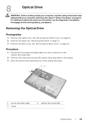
... your computer and follow the steps in "Before You Begin" on page 19. For additional safety best practices information, see the Regulatory Compliance Homepage at dell.com/regulatory_compliance.
... your computer and follow the steps in "Before You Begin" on page 19. For additional safety best practices information, see the Regulatory Compliance Homepage at dell.com/regulatory_compliance.
