
Specifications (SWF/PDF)
Page 4
10 Converter Board 29 Removing the Converter Board 29 Replacing the Converter Board 30 11 Memory Module(s 31 Removing the Memory Module(s 31 Replacing the Memory Module(s 33 12 System-Board Shield 35 Removing the System-Board Shield 35 Replacing the System-Board Shield 36 13 Antenna-In Connector 37 Removing ...
10 Converter Board 29 Removing the Converter Board 29 Replacing the Converter Board 30 11 Memory Module(s 31 Removing the Memory Module(s 31 Replacing the Memory Module(s 33 12 System-Board Shield 35 Removing the System-Board Shield 35 Replacing the System-Board Shield 36 13 Antenna-In Connector 37 Removing ...
Specifications (SWF/PDF)
Page 7
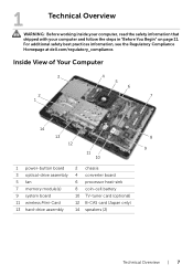
... Begin" on page 11. For additional safety best practices information, see the Regulatory Compliance Homepage at dell.com/regulatory_compliance. Inside View of Your Computer 3 2 1 4 5 6 7 14 13 8 12 9 11 10 1 power-button board 3 optical-drive assembly 5 fan 7 memory module(s) 9 system board 11 wireless Mini-Card 13 hard-drive assembly 2 chassis 4 converter board 6 processor...
... Begin" on page 11. For additional safety best practices information, see the Regulatory Compliance Homepage at dell.com/regulatory_compliance. Inside View of Your Computer 3 2 1 4 5 6 7 14 13 8 12 9 11 10 1 power-button board 3 optical-drive assembly 5 fan 7 memory module(s) 9 system board 11 wireless Mini-Card 13 hard-drive assembly 2 chassis 4 converter board 6 processor...
Specifications (SWF/PDF)
Page 9
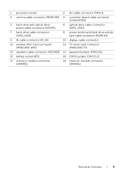
...) 12 TV-tuner card connector (MINICARD TV) 13 speakers cable connector (SPEAKER) 14 password jumper (PWCLR1) 15 battery socket (BT1) 16 CMOS jumper (CMOCL1) 17 memory-module connector (DIMMB1) 18 memory-module connector (DIMMA1) Technical Overview | 9
...) 12 TV-tuner card connector (MINICARD TV) 13 speakers cable connector (SPEAKER) 14 password jumper (PWCLR1) 15 battery socket (BT1) 16 CMOS jumper (CMOCL1) 17 memory-module connector (DIMMB1) 18 memory-module connector (DIMMA1) Technical Overview | 9
Specifications (SWF/PDF)
Page 31
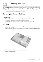
...Remove the stand. For additional safety best practices information, see the Regulatory Compliance Homepage at dell.com/regulatory_compliance. See "Removing the Back Cover" on page 17. 3 Remove the back cover. 11 Memory Module(s) WARNING: Before working inside your computer, read the safety information that secures the... memory-module shield to the system-board shield. 2 Slide the memory-module shield toward the top of the computer, and lift ...
...Remove the stand. For additional safety best practices information, see the Regulatory Compliance Homepage at dell.com/regulatory_compliance. See "Removing the Back Cover" on page 17. 3 Remove the back cover. 11 Memory Module(s) WARNING: Before working inside your computer, read the safety information that secures the... memory-module shield to the system-board shield. 2 Slide the memory-module shield toward the top of the computer, and lift ...
Specifications (SWF/PDF)
Page 32
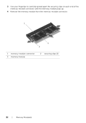
3 Use your fingertips to carefully spread apart the securing clips on each end of the memory-module connector until the memory module pops up. 4 Remove the memory module from the memory-module connector. 1 3 2 1 memory-module connector 3 memory module 2 securing clips (2) 32 | Memory Module(s)
3 Use your fingertips to carefully spread apart the securing clips on each end of the memory-module connector until the memory module pops up. 4 Remove the memory module from the memory-module connector. 1 3 2 1 memory-module connector 3 memory module 2 securing clips (2) 32 | Memory Module(s)
Specifications (SWF/PDF)
Page 33
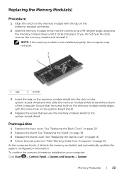
... See "Replacing the Stand Cover" on page 16. 4 Follow the instructions in "After Working Inside Your Computer" on page 13. Replacing the Memory Module(s) Procedure 1 Align the notch on the memory module with the screw hole on the system-board shield. 4 Replace the screw that the screw hole on the... memory-module shield aligns with the tab on the memory-module connector. 2 Slide the memory module firmly into the connector at a 45-degree angle, and press the memory module down until it clicks into the slots on the system-board shield...
... See "Replacing the Stand Cover" on page 16. 4 Follow the instructions in "After Working Inside Your Computer" on page 13. Replacing the Memory Module(s) Procedure 1 Align the notch on the memory module with the screw hole on the system-board shield. 4 Replace the screw that the screw hole on the... memory-module shield aligns with the tab on the memory-module connector. 2 Slide the memory module firmly into the connector at a 45-degree angle, and press the memory module down until it clicks into the slots on the system-board shield...

Specifications (SWF/PDF)
Page 34
34 | Memory Module(s)
34 | Memory Module(s)

Specifications (SWF/PDF)
Page 69
... the Stand" on page 35. 5 Remove the memory module(s). See "Removing the System-Board Shield" on page 17. 3 Remove the back cover. See "Removing the TV-Tuner Card" on page 65. For additional safety best practices information, see the Regulatory Compliance Homepage at dell.com/regulatory_compliance. Removing the System Board Prerequisites 1 Remove...
... the Stand" on page 35. 5 Remove the memory module(s). See "Removing the System-Board Shield" on page 17. 3 Remove the back cover. See "Removing the TV-Tuner Card" on page 65. For additional safety best practices information, see the Regulatory Compliance Homepage at dell.com/regulatory_compliance. Removing the System Board Prerequisites 1 Remove...
Specifications (SWF/PDF)
Page 71
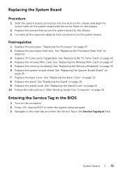
... 18. 9 Replace the stand cover. See "Replacing the Wireless Mini-Card" on page 33. 6 Replace the system-board shield. See "Replacing the Memory Module(s)" on page 47. 5 Replace the memory module(s). Replacing the System Board Procedure 1 Slide the system board connectors into the slots on the chassis and align the screw holes...
... 18. 9 Replace the stand cover. See "Replacing the Wireless Mini-Card" on page 33. 6 Replace the system-board shield. See "Replacing the Memory Module(s)" on page 47. 5 Replace the memory module(s). Replacing the System Board Procedure 1 Slide the system board connectors into the slots on the chassis and align the screw holes...

Specifications (SWF/PDF)
Page 97
Memory Information Memory Installed Memory Running Speed Memory Technology Indicates the amount of memory installed in MB Indicates the memory speed in MHz Indicates the type of the computer when the asset tag is present Main - Main - System Information BIOS Revision BIOS Build Date System ... the computer Allows you to enter the Service Tag of the computer if the Service Tag field is empty Displays the asset tag of installed memory System Setup | 97
Memory Information Memory Installed Memory Running Speed Memory Technology Indicates the amount of memory installed in MB Indicates the memory speed in MHz Indicates the type of the computer when the asset tag is present Main - Main - System Information BIOS Revision BIOS Build Date System ... the computer Allows you to enter the Service Tag of the computer if the Service Tag field is empty Displays the asset tag of installed memory System Setup | 97
Specifications (SWF/PDF)
Page 104
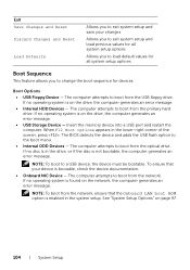
... the drive, the computer generates an error message. • Internal HDD Devices - If no operating system is on page 97. 104 | System Setup Insert the memory device into a USB port and restart the computer. If no operating system is found on the drive, the computer generates an error message. • USB...
... the drive, the computer generates an error message. • Internal HDD Devices - If no operating system is on page 97. 104 | System Setup Insert the memory device into a USB port and restart the computer. If no operating system is found on the drive, the computer generates an error message. • USB...
Specifications (SWF/PDF)
Page 105
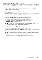
...the menu. For example, if you see the Microsoft Windows desktop. Changing Boot Sequence for example, to boot from the optical drive to run Dell Diagnostics from . Changing Boot Sequence for the Current Boot You can use this feature to change the boot priority of the device. NOTE: ... tests, the previous boot sequence is bootable, check the device documentation. Then shut down your device is restored. 1 If you want to a USB memory key, highlight USB Storage Device and press . The Boot Device Menu appears, listing all available boot devices. 4 On the Boot Device Menu choose the...
...the menu. For example, if you see the Microsoft Windows desktop. Changing Boot Sequence for example, to boot from the optical drive to run Dell Diagnostics from . Changing Boot Sequence for the Current Boot You can use this feature to change the boot priority of the device. NOTE: ... tests, the previous boot sequence is bootable, check the device documentation. Then shut down your device is restored. 1 If you want to a USB memory key, highlight USB Storage Device and press . The Boot Device Menu appears, listing all available boot devices. 4 On the Boot Device Menu choose the...


