Specifications (SWF/PDF)
Page 3
Contents 1 Technical Overview 7 Inside View of Your Computer 7 System Board Components 8 2 Before You Begin 11 Turn Off Your Computer and Connected Devices 11 Safety Instructions 11 Recommended Tools 12 3 After Working Inside Your Computer 13 4 Stand Cover 15 Removing the Stand Cover 15 Replacing the Stand ...
Contents 1 Technical Overview 7 Inside View of Your Computer 7 System Board Components 8 2 Before You Begin 11 Turn Off Your Computer and Connected Devices 11 Safety Instructions 11 Recommended Tools 12 3 After Working Inside Your Computer 13 4 Stand Cover 15 Removing the Stand Cover 15 Replacing the Stand ...
Specifications (SWF/PDF)
Page 11
... button for about safety precautions, working inside your computer, ground yourself by their electrical outlets. 4 Disconnect all power sources before connecting to dissipate static electricity, which could harm internal components. See the safety instructions for shut-down and then the computer turns off...panels. CAUTION: To avoid damaging the components and cards, handle them by touching an unpainted metal surface, such as the metal at dell.com/regulatory_compliance. While you turn off . CAUTION: To avoid damaging the computer, ensure that shipped with your computer. 1 Save ...
... button for about safety precautions, working inside your computer, ground yourself by their electrical outlets. 4 Disconnect all power sources before connecting to dissipate static electricity, which could harm internal components. See the safety instructions for shut-down and then the computer turns off...panels. CAUTION: To avoid damaging the components and cards, handle them by touching an unpainted metal surface, such as the metal at dell.com/regulatory_compliance. While you turn off . CAUTION: To avoid damaging the computer, ensure that shipped with your computer. 1 Save ...
Specifications (SWF/PDF)
Page 12
When connecting cables, ensure that you disconnect a cable, pull on its connector or on its pull-tab, not on the cable itself. CAUTION: To disconnect a network cable, ...
When connecting cables, ensure that you disconnect a cable, pull on its connector or on its pull-tab, not on the cable itself. CAUTION: To disconnect a network cable, ...
Specifications (SWF/PDF)
Page 13
3 After Working Inside Your Computer After you removed before working on your computer • Connect your computer and all attached devices to do so may damage your computer. Failure to their electrical outlets CAUTION: Before turning on your computer, replace... all screws and ensure that no stray screws remain inside your computer • Place the computer in an upright position • Connect any external devices, cables, cards, and any other part(s) you complete replacement procedures, ensure the following: • Replace all screws and ensure that no ...
3 After Working Inside Your Computer After you removed before working on your computer • Connect your computer and all attached devices to do so may damage your computer. Failure to their electrical outlets CAUTION: Before turning on your computer, replace... all screws and ensure that no stray screws remain inside your computer • Place the computer in an upright position • Connect any external devices, cables, cards, and any other part(s) you complete replacement procedures, ensure the following: • Replace all screws and ensure that no ...
Specifications (SWF/PDF)
Page 23
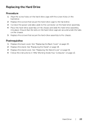
... the hard-drive cage are secured under the tabs on the chassis. 5 Replace the screws that secure the hard-drive cage to the hard drive. 3 Connect the power and data cable to the chassis. See "Replacing the Back Cover" on page 20. 2 Replace the stand. Replacing the Hard Drive Procedure 1 Align...
... the hard-drive cage are secured under the tabs on the chassis. 5 Replace the screws that secure the hard-drive cage to the hard drive. 3 Connect the power and data cable to the chassis. See "Replacing the Back Cover" on page 20. 2 Replace the stand. Replacing the Hard Drive Procedure 1 Align...
Specifications (SWF/PDF)
Page 26
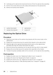
... optical-drive assembly into the optical-drive bay until it is fully seated. 5 Replace the screw that secures the optical-drive assembly to the chassis. 6 Connect the power and data cable to the connector on page 20. 2 Replace the stand. See "Replacing the Back Cover" on the optical-drive assembly.
... optical-drive assembly into the optical-drive bay until it is fully seated. 5 Replace the screw that secures the optical-drive assembly to the chassis. 6 Connect the power and data cable to the connector on page 20. 2 Replace the stand. See "Replacing the Back Cover" on the optical-drive assembly.
Specifications (SWF/PDF)
Page 28
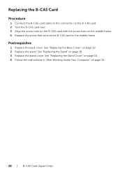
...) See "Replacing the Stand" on the middle frame. 4 Replace the screw that secures the B-CAS card to the middle frame. Replacing the B-CAS Card Procedure 1 Connect the B-CAS-card cable to the connector on the B-CAS card. 2 Turn the B-CAS card over. 3 Align the screw hole on the B-CAS card with...
...) See "Replacing the Stand" on the middle frame. 4 Replace the screw that secures the B-CAS card to the middle frame. Replacing the B-CAS Card Procedure 1 Connect the B-CAS-card cable to the connector on the B-CAS card. 2 Turn the B-CAS card over. 3 Align the screw hole on the B-CAS card with...

Specifications (SWF/PDF)
Page 30
Postrequisites 1 Replace the back cover. See "Replacing the Stand" on page 13. 30 | Converter Board See "Replacing the Stand Cover" on page 16. 4 Follow the instructions in "After Working Inside Your Computer" on page 18. 3 Replace the stand cover. See "Replacing the Back Cover" on the converter board. Replacing the Converter Board Procedure 1 Align the screw holes on the converter board with the screw holes on the chassis. 2 Replace the screws that secure the converter board to the chassis. 3 Connect the cables to the connectors on page 20. 2 Replace the stand.
Postrequisites 1 Replace the back cover. See "Replacing the Stand" on page 13. 30 | Converter Board See "Replacing the Stand Cover" on page 16. 4 Follow the instructions in "After Working Inside Your Computer" on page 18. 3 Replace the stand cover. See "Replacing the Back Cover" on the converter board. Replacing the Converter Board Procedure 1 Align the screw holes on the converter board with the screw holes on the chassis. 2 Replace the screws that secure the converter board to the chassis. 3 Connect the cables to the connectors on page 20. 2 Replace the stand.
Specifications (SWF/PDF)
Page 36
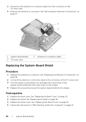
...-tuner card. 3 Turn the system-board shield over and align the screw holes on the system-board shield with the screw holes on page 38. 2 Connect the antenna-in connector. See "Replacing the Back Cover" on page 18. 3 Replace the stand cover. See "Replacing the Antenna-In Connector" on the chassis...
...-tuner card. 3 Turn the system-board shield over and align the screw holes on the system-board shield with the screw holes on page 38. 2 Connect the antenna-in connector. See "Replacing the Back Cover" on page 18. 3 Replace the stand cover. See "Replacing the Antenna-In Connector" on the chassis...

Specifications (SWF/PDF)
Page 40
... 1 Replace the system-board shield. Replacing the Antenna Modules Procedure 1 Adhere the antenna modules to the chassis. 2 Route the antenna cables through the routing guides. 3 Connect the antenna cables to the connectors on the wireless Mini-Card.
... 1 Replace the system-board shield. Replacing the Antenna Modules Procedure 1 Adhere the antenna modules to the chassis. 2 Route the antenna cables through the routing guides. 3 Connect the antenna cables to the connectors on the wireless Mini-Card.

Specifications (SWF/PDF)
Page 43
.... 3 Press the other end of the TV-tuner card down and replace the screw that secures the TV-tuner card to the system-board connector. 4 Connect the TV-tuner-card cable to the connector on the TV-tuner card.
.... 3 Press the other end of the TV-tuner card down and replace the screw that secures the TV-tuner card to the system-board connector. 4 Connect the TV-tuner-card cable to the connector on the TV-tuner card.

Specifications (SWF/PDF)
Page 47
The Mini-Card has two triangles (black and white) marked on the label: • Connect the black cable to the connector marked with a black triangle. • Connect the white cable to the Mini-Card, ensure that there are no cables under the Mini-Card. 1 Align the notch on the Mini-...Card with a white triangle. Use of the Mini-Card down and replace the screw that secures the Mini-Card to the system-board connector. 4 Connect the appropriate antenna cables to the Mini-Card you are keyed to ensure correct insertion. Wireless Mini-Card (Optional) | 47 Postrequisites 1 Replace the system...
The Mini-Card has two triangles (black and white) marked on the label: • Connect the black cable to the connector marked with a black triangle. • Connect the white cable to the Mini-Card, ensure that there are no cables under the Mini-Card. 1 Align the notch on the Mini-...Card with a white triangle. Use of the Mini-Card down and replace the screw that secures the Mini-Card to the system-board connector. 4 Connect the appropriate antenna cables to the Mini-Card you are keyed to ensure correct insertion. Wireless Mini-Card (Optional) | 47 Postrequisites 1 Replace the system...

Specifications (SWF/PDF)
Page 53
... screw holes on the middle frame. 2 Replace the screws that secure the speakers to the middle frame. 3 Route the speakers cable through the routing guides. 4 Connect the speakers cable to the connector (SPEAKER) on page 20. 4 Replace the stand. See "Replacing the B-CAS Card" on page 18. 5 Replace the stand cover...
... screw holes on the middle frame. 2 Replace the screws that secure the speakers to the middle frame. 3 Route the speakers cable through the routing guides. 4 Connect the speakers cable to the connector (SPEAKER) on page 20. 4 Replace the stand. See "Replacing the B-CAS Card" on page 18. 5 Replace the stand cover...
Specifications (SWF/PDF)
Page 56
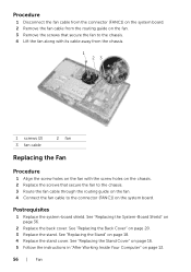
... holes on the chassis. 2 Replace the screws that secure the fan to the chassis. 3 Route the fan cable through the routing guide on the fan. 4 Connect the fan cable to the connector (FANC1) on page 18. 4 Replace the stand cover. Postrequisites 1 Replace the system-board shield. See "Replacing the Stand Cover...
... holes on the chassis. 2 Replace the screws that secure the fan to the chassis. 3 Route the fan cable through the routing guide on the fan. 4 Connect the fan cable to the connector (FANC1) on page 18. 4 Replace the stand cover. Postrequisites 1 Replace the system-board shield. See "Replacing the Stand Cover...
Specifications (SWF/PDF)
Page 59
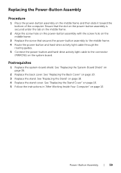
... screw that secures the power-button assembly to the middle frame. 4 Route the power-button and hard-drive activity light cable through the routing guides. 5 Connect the power-button and hard-drive activity light cable to the connector (PWRCN1) on page 36. 2 Replace the back cover.
... screw that secures the power-button assembly to the middle frame. 4 Route the power-button and hard-drive activity light cable through the routing guides. 5 Connect the power-button and hard-drive activity light cable to the connector (PWRCN1) on page 36. 2 Replace the back cover.
Specifications (SWF/PDF)
Page 71
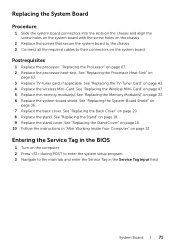
... the screw holes on the system board with the screw holes on the chassis. 2 Replace the screws that secure the system board to the chassis. 3 Connect all the required cables to the main tab and enter the Service Tag in the Service Tag Input field. See "Replacing the TV-Tuner Card...
... the screw holes on the system board with the screw holes on the chassis. 2 Replace the screws that secure the system board to the chassis. 3 Connect all the required cables to the main tab and enter the Service Tag in the Service Tag Input field. See "Replacing the TV-Tuner Card...
Specifications (SWF/PDF)
Page 77
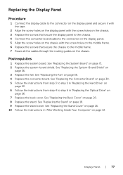
... the screw holes on the display panel with the screw holes on the chassis. 3 Replace the screws that secure the display panel to the chassis. 4 Connect the converter-board cable to the connector on the display panel. 5 Align the screw holes on the chassis with the screw holes on the middle...
... the screw holes on the display panel with the screw holes on the chassis. 3 Replace the screws that secure the display panel to the chassis. 4 Connect the converter-board cable to the connector on the display panel. 5 Align the screw holes on the chassis with the screw holes on the middle...
Specifications (SWF/PDF)
Page 95
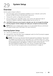
Entering System Setup 1 Turn on (or restart) your computer. 2 During POST, when the DELL logo is lost. This prompt can make your computer work incorrectly. NOTE: The F2 prompt indicates that you write down the system setup screen information ... so on CAUTION: Unless you are an expert computer user, do not change system setup, it , and then press . See "Turn Off Your Computer and Connected Devices" on page 11. NOTE: Before you press before the F2 prompt, this program. Certain changes can appear very quickly, so you see the Microsoft...
Entering System Setup 1 Turn on (or restart) your computer. 2 During POST, when the DELL logo is lost. This prompt can make your computer work incorrectly. NOTE: The F2 prompt indicates that you write down the system setup screen information ... so on CAUTION: Unless you are an expert computer user, do not change system setup, it , and then press . See "Turn Off Your Computer and Connected Devices" on page 11. NOTE: Before you press before the F2 prompt, this program. Certain changes can appear very quickly, so you see the Microsoft...
Specifications (SWF/PDF)
Page 98
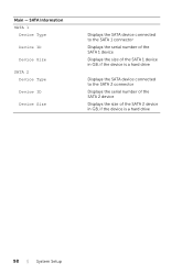
Main - SATA Information SATA 1 Device Type Device ID Device Size SATA 2 Device Type Device ID Device Size Displays the SATA device connected to the SATA 1 connector Displays the serial number of the SATA 1 device Displays the size of the SATA 1 device in GB, if the device is a hard drive Displays the SATA device connected to the SATA 2 connector Displays the serial number of the SATA 2 device Displays the size of the SATA 2 device in GB, if the device is a hard drive 98 | System Setup
Main - SATA Information SATA 1 Device Type Device ID Device Size SATA 2 Device Type Device ID Device Size Displays the SATA device connected to the SATA 1 connector Displays the serial number of the SATA 1 device Displays the size of the SATA 1 device in GB, if the device is a hard drive Displays the SATA device connected to the SATA 2 connector Displays the serial number of the SATA 2 device Displays the size of the SATA 2 device in GB, if the device is a hard drive 98 | System Setup
Specifications (SWF/PDF)
Page 105
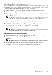
... shut down your computer and try again. To ensure your computer. 3 When F2 Setup, F12 Boot Options appears in case you are booting to run Dell Diagnostics from . NOTE: Write down your current boot sequence in the lower-right corner of the device. See "Entering System Setup" on (or restart)...disc. The Boot Device Menu appears, listing all available boot devices. 4 On the Boot Device Menu choose the device you are booting from a USB device, connect the USB device to a USB port. 2 Turn on page 95. 2 Use the arrow keys to highlight the Boot menu option and press to restore ...
... shut down your computer and try again. To ensure your computer. 3 When F2 Setup, F12 Boot Options appears in case you are booting to run Dell Diagnostics from . NOTE: Write down your current boot sequence in the lower-right corner of the device. See "Entering System Setup" on (or restart)...disc. The Boot Device Menu appears, listing all available boot devices. 4 On the Boot Device Menu choose the device you are booting from a USB device, connect the USB device to a USB port. 2 Turn on page 95. 2 Use the arrow keys to highlight the Boot menu option and press to restore ...


