
User Manual
Page 7
...; Before installing the motherboard and adding devices on a stable surface. • If you add a device. • Before connecting or removing signal cables from connectors, slots, sockets and circuitry. • Avoid dust, humidity, and temperature extremes. Safety information Electrical safety • To prevent electric shock hazard, disconnect the power cable from the...
...; Before installing the motherboard and adding devices on a stable surface. • If you add a device. • Before connecting or removing signal cables from connectors, slots, sockets and circuitry. • Avoid dust, humidity, and temperature extremes. Safety information Electrical safety • To prevent electric shock hazard, disconnect the power cable from the...
User Manual
Page 9
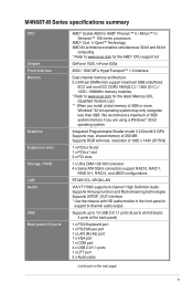
..., Windows® 32-bit operating system may only recognize less than 3GB. M4N68T-M Series specifications summary CPU Chipset Front side bus Memory Graphics Expansion slots Storage / RAID LAN ...Audio USB Back panel I/O ports AMD® Socket AM3 for AMD® Phenom™ II / Athlon™ II / Sempron™ 100...Cool 'n' Quiet™ Technology AMD 64 architecture enables simultaneous 32-bit and 64-bit computing * Refer to www.asus.com for the AMD® CPU support list GeForce 7025 / nForce 630a 2000 / 1600 MT/s HyperTransport™...
..., Windows® 32-bit operating system may only recognize less than 3GB. M4N68T-M Series specifications summary CPU Chipset Front side bus Memory Graphics Expansion slots Storage / RAID LAN ...Audio USB Back panel I/O ports AMD® Socket AM3 for AMD® Phenom™ II / Athlon™ II / Sempron™ 100...Cool 'n' Quiet™ Technology AMD 64 architecture enables simultaneous 32-bit and 64-bit computing * Refer to www.asus.com for the AMD® CPU support list GeForce 7025 / nForce 630a 2000 / 1600 MT/s HyperTransport™...
User Manual
Page 11
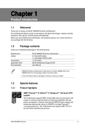
... support This motherboard supports AMD® Socket AM3 multi-core processors with unique L3 cache and delivers better overclocking capabilities with the list below. 1.2 Package contents Check your package with less power consumption. Before you for the following items. Motherboard Cables Accessories Application DVD Documentation ASUS M4N68T-M Series motherboard 2 x Serial ATA cables 1 x Ultra...
... support This motherboard supports AMD® Socket AM3 multi-core processors with unique L3 cache and delivers better overclocking capabilities with the list below. 1.2 Package contents Check your package with less power consumption. Before you for the following items. Motherboard Cables Accessories Application DVD Documentation ASUS M4N68T-M Series motherboard 2 x Serial ATA cables 1 x Ultra...
User Manual
Page 15
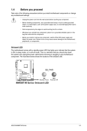
... location of the following precautions before you install motherboard components or change any motherboard settings. • Unplug the power cord from the wall socket before touching any component. • Before handling components, use a grounded wrist strap or touch a safely grounded object or a metal object... before removing or plugging in soft-off the ATX power supply and detach its power cord. SB_PWR M4N68T-M V2 ON OFF Standby Power Powered Off M4N68T-M Series Onboard LED ASUS M4N68T-M Series 1-5 Failure to do so may cause severe damage to indicate that the system is a ...
... location of the following precautions before you install motherboard components or change any motherboard settings. • Unplug the power cord from the wall socket before touching any component. • Before handling components, use a grounded wrist strap or touch a safely grounded object or a metal object... before removing or plugging in soft-off the ATX power supply and detach its power cord. SB_PWR M4N68T-M V2 ON OFF Standby Power Powered Off M4N68T-M Series Onboard LED ASUS M4N68T-M Series 1-5 Failure to do so may cause severe damage to indicate that the system is a ...
User Manual
Page 17
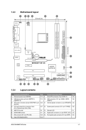
...24-pin EATXPWR, 4-pin 1-22 11. CPU and chassis fan connectors (4-pin CPU_FAN and 3-pin CHA_FAN) 1-27 12. Clear RTC RAM (CLRTC) 1-18 ASUS M4N68T-M Series 1-7 USB connectors (10-1 pin USB56, USB78, 1-26 USB910) 3. System panel connector (10-1 pin F_PANEL) 1-25 5. IDE connector (40-1... pin PRI_IDE) 1-23 15. AMD CPU socket 1-8 13. Front panel audio connector (10-1 pin AAFP) 1-21 8. DDR3 DIMM sockets 1-11 14. 1.5.3 Motherboard layout 1 23 4 5 6 20.8cm(8.2in) KB/MS KBPWR ATX12V COM1 DDR3 DIMM_A1 (...
...24-pin EATXPWR, 4-pin 1-22 11. CPU and chassis fan connectors (4-pin CPU_FAN and 3-pin CHA_FAN) 1-27 12. Clear RTC RAM (CLRTC) 1-18 ASUS M4N68T-M Series 1-7 USB connectors (10-1 pin USB56, USB78, 1-26 USB910) 3. System panel connector (10-1 pin F_PANEL) 1-25 5. IDE connector (40-1... pin PRI_IDE) 1-23 15. AMD CPU socket 1-8 13. Front panel audio connector (10-1 pin AAFP) 1-21 8. DDR3 DIMM sockets 1-11 14. 1.5.3 Motherboard layout 1 23 4 5 6 20.8cm(8.2in) KB/MS KBPWR ATX12V COM1 DDR3 DIMM_A1 (...
User Manual
Page 18
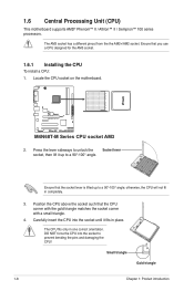
... that the CPU corner with the gold triangle matches the socket corner with a small triangle. 4. Locate the CPU socket on the motherboard. Small triangle Gold triangle 1-8 Chapter 1: Product introduction M4N68T-M V2 M4N68T-M Series CPU socket AM3 2. DO NOT force the CPU into the socket until it up to prevent bending the pins and damaging the CPU...
... that the CPU corner with the gold triangle matches the socket corner with a small triangle. 4. Locate the CPU socket on the motherboard. Small triangle Gold triangle 1-8 Chapter 1: Product introduction M4N68T-M V2 M4N68T-M Series CPU socket AM3 2. DO NOT force the CPU into the socket until it up to prevent bending the pins and damaging the CPU...
User Manual
Page 19
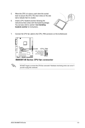
...push down the socket lever to the CPU_FAN connector on the side tab to connect the CPU fan connector! You can occur if you fail to section 1.6.2 Installing heatsink and fan for instructions. 7. Hardware monitoring errors can also refer to plug this connector. ASUS M4N68T-M Series 1-9... The lever clicks on the motherboard. M4N68T-M V2 CPU_FAN CPU FAN PWM CPU FAN IN CPU FAN PWR GND M4N68T-M Series CPU fan connector DO NOT forget to indicate that comes with the heatsink...
...push down the socket lever to the CPU_FAN connector on the side tab to connect the CPU fan connector! You can occur if you fail to section 1.6.2 Installing heatsink and fan for instructions. 7. Hardware monitoring errors can also refer to plug this connector. ASUS M4N68T-M Series 1-9... The lever clicks on the motherboard. M4N68T-M V2 CPU_FAN CPU FAN PWM CPU FAN IN CPU FAN PWR GND M4N68T-M Series CPU fan connector DO NOT forget to indicate that comes with the heatsink...
User Manual
Page 21
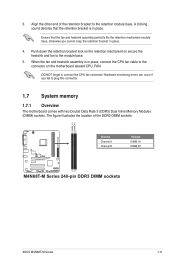
.... 5. Push down the retention bracket lock on the motherboard labeled CPU_FAN. Align the other end of the DDR3 DIMM sockets: DIMM_A1 DIMM_B1 M4N68T-M V2 Channel Channel A Channel B Sockets DIMM_A1 DIMM_B1 M4N68T-M Series 240-pin DDR3 DIMM sockets ASUS M4N68T-M Series 1-11 The figure illustrates the location of the retention bracket to plug this connector. 1.7 System memory 1.7.1 Overview...
.... 5. Push down the retention bracket lock on the motherboard labeled CPU_FAN. Align the other end of the DDR3 DIMM sockets: DIMM_A1 DIMM_B1 M4N68T-M V2 Channel Channel A Channel B Sockets DIMM_A1 DIMM_B1 M4N68T-M Series 240-pin DDR3 DIMM sockets ASUS M4N68T-M Series 1-11 The figure illustrates the location of the retention bracket to plug this connector. 1.7 System memory 1.7.1 Overview...
User Manual
Page 22
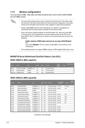
...Corsair Crucial Crucial Crucial Crucial Crucial Crucial Part No. Apacer 78.0AGCD.CDZ(XMP) 2048MB(Kit of 3) SS/ DS Brand Chip NO. M4N68T-M Series Motherboard Qualified Vendors Lists (QVL) DDR3-1800(O.C.)MHz capability Vendor Part No. 1.7.2 Memory configurations You may install 512MB, 1GB, 2GB,... and 4GB unbuffered ECC and non-ECC DDR3 DIMMs into the DIMM sockets. • You may install varying memory sizes in ��g�a��3�2�-�b�it�W��i�...
...Corsair Crucial Crucial Crucial Crucial Crucial Crucial Part No. Apacer 78.0AGCD.CDZ(XMP) 2048MB(Kit of 3) SS/ DS Brand Chip NO. M4N68T-M Series Motherboard Qualified Vendors Lists (QVL) DDR3-1800(O.C.)MHz capability Vendor Part No. 1.7.2 Memory configurations You may install 512MB, 1GB, 2GB,... and 4GB unbuffered ECC and non-ECC DDR3 DIMMs into the DIMM sockets. • You may install varying memory sizes in ��g�a��3�2�-�b�it�W��i�...
User Manual
Page 26
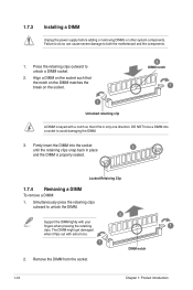
... Retaining Clip 1.7.4 Removing a DIMM To remove a DIMM: 1. Failure to do so can cause severe damage to unlock a DIMM socket. 2. Firmly insert the DIMM into a socket to unlock the DIMM. 2 Support the DIMM lightly with extra force. 1 DIMM notch 2. The DIMM might get damaged when it...DIMM is keyed with a notch so that it flips out with your fingers when pressing the retaining 1 clips. Remove the DIMM from the socket. 1-16 Chapter 1: Product introduction Simultaneously press the retaining clips outward to avoid damaging the DIMM. 3. Press the retaining clips outward to ...
... Retaining Clip 1.7.4 Removing a DIMM To remove a DIMM: 1. Failure to do so can cause severe damage to unlock a DIMM socket. 2. Firmly insert the DIMM into a socket to unlock the DIMM. 2 Support the DIMM lightly with extra force. 1 DIMM notch 2. The DIMM might get damaged when it...DIMM is keyed with a notch so that it flips out with your fingers when pressing the retaining 1 clips. Remove the DIMM from the socket. 1-16 Chapter 1: Product introduction Simultaneously press the retaining clips outward to avoid damaging the DIMM. 3. Press the retaining clips outward to ...


