
User Manual
Page 3
Contents Notices...vi Safety information vii About this guide vii M4N68T-M Series specifications summary ix Chapter 1: Product introduction 1.1 Welcome 1-1 1.2 Package contents 1-1 1.3 Special features 1-1 1.3.1 Product highlights 1-1 1.3.2 Innovative ASUS features 1-3 1.4 Before you proceed 1-5 1.5 Motherboard overview 1-6 1.5.1 Placement direction 1-6 1.5.2 Screw holes 1-6 1.5.3 Motherboard layout 1-7 1.5.4 Layout contents 1-7 1.6 Central Processing Unit (CPU 1-8 1.6.1 Installing the CPU 1-8 1.6.2 Installing the heatsink and fan 1-10 1.7 System...
Contents Notices...vi Safety information vii About this guide vii M4N68T-M Series specifications summary ix Chapter 1: Product introduction 1.1 Welcome 1-1 1.2 Package contents 1-1 1.3 Special features 1-1 1.3.1 Product highlights 1-1 1.3.2 Innovative ASUS features 1-3 1.4 Before you proceed 1-5 1.5 Motherboard overview 1-6 1.5.1 Placement direction 1-6 1.5.2 Screw holes 1-6 1.5.3 Motherboard layout 1-7 1.5.4 Layout contents 1-7 1.6 Central Processing Unit (CPU 1-8 1.6.1 Installing the CPU 1-8 1.6.2 Installing the heatsink and fan 1-10 1.7 System...
User Manual
Page 6
... equipment and receiver. • Connect the equipment to an outlet on a circuit different from digital apparatus set out in our products at ASUS REACH website at http://csr.asus.com/english/REACH.htm. Operation is subject to radio or television reception, which the receiver is no guarantee that may not cause harmful... will not occur in municipal waste. Changes or modifications to this unit not expressly approved by one or more of Communications. DO NOT throw the motherboard in a particular installation.
... equipment and receiver. • Connect the equipment to an outlet on a circuit different from digital apparatus set out in our products at ASUS REACH website at http://csr.asus.com/english/REACH.htm. Operation is subject to radio or television reception, which the receiver is no guarantee that may not cause harmful... will not occur in municipal waste. Changes or modifications to this unit not expressly approved by one or more of Communications. DO NOT throw the motherboard in a particular installation.
User Manual
Page 7
...Avoid dust, humidity, and temperature extremes. How this guide This user guide contains the information you need when installing and configuring the motherboard. Detailed descriptions of the BIOS parameters are connected. If possible, disconnect all power cables from the existing system before you encounter technical ... of the electrical outlet you detect any area where it by yourself. If you are not sure about the voltage of the motherboard and the new technology it , carefully read all the manuals that came with the product, contact a qualified service technician or your...
...Avoid dust, humidity, and temperature extremes. How this guide This user guide contains the information you need when installing and configuring the motherboard. Detailed descriptions of the BIOS parameters are connected. If possible, disconnect all power cables from the existing system before you encounter technical ... of the electrical outlet you detect any area where it by yourself. If you are not sure about the voltage of the motherboard and the new technology it , carefully read all the manuals that came with the product, contact a qualified service technician or your...
User Manual
Page 11
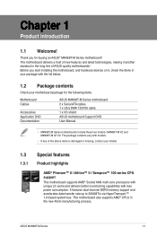
... long line of the above items is damaged or missing, contact your motherboard package for buying an ASUS® M4N68T-M Series motherboard! ASUS M4N68T-M Series 1-1 Thank you start installing the motherboard, and hardware devices on it another standout in the new 45nm manufacturing process. The motherboard delivers a host of new features and latest technologies, making it , check the...
... long line of the above items is damaged or missing, contact your motherboard package for buying an ASUS® M4N68T-M Series motherboard! ASUS M4N68T-M Series 1-1 Thank you start installing the motherboard, and hardware devices on it another standout in the new 45nm manufacturing process. The motherboard delivers a host of new features and latest technologies, making it , check the...
User Manual
Page 12
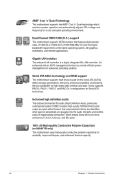
... 1800 (O.C.)/1600 (O.C.)/1333/1066 MHz to provide efficient power management for advanced operating systems. Serial ATA 3Gb/s technology and RAID support This motherboard supports hard drives based on M4N68T-M only) This motherboard uses high-quality conductive polymer capacitors for durability, improved lifespan, and enhanced thermal capacity. 1-2 Chapter 1: Product introduction Dual-Channel DDR3 1800...
... 1800 (O.C.)/1600 (O.C.)/1333/1066 MHz to provide efficient power management for advanced operating systems. Serial ATA 3Gb/s technology and RAID support This motherboard supports hard drives based on M4N68T-M only) This motherboard uses high-quality conductive polymer capacitors for durability, improved lifespan, and enhanced thermal capacity. 1-2 Chapter 1: Product introduction Dual-Channel DDR3 1800...
User Manual
Page 13
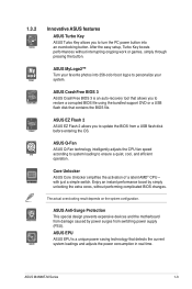
...a USB flash disk that detects the current system loadings and adjusts the power consumption in real time. ASUS M4N68T-M Series 1-3 1.3.2 Innovative ASUS features ASUS Turbo Key ASUS Turbo Key allows you to turn the PC power button into 256-color boot logos to personalize your system...USB flash disk before entering the OS. The actual overclocking result depends on the system configuration. ASUS Anti-Surge Protection This special design prevents expensive devices and the motherboard from damage caused by simply unlocking the extra cores, without interrupting ongoing work or games, ...
...a USB flash disk that detects the current system loadings and adjusts the power consumption in real time. ASUS M4N68T-M Series 1-3 1.3.2 Innovative ASUS features ASUS Turbo Key ASUS Turbo Key allows you to turn the PC power button into 256-color boot logos to personalize your system...USB flash disk before entering the OS. The actual overclocking result depends on the system configuration. ASUS Anti-Surge Protection This special design prevents expensive devices and the motherboard from damage caused by simply unlocking the extra cores, without interrupting ongoing work or games, ...
User Manual
Page 14
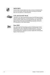
... default settings when the system hangs due to open the system chassis and clear the RTC data. Green ASUS This motherboard and its packaging comply with the ASUS vision of Hazardous Substances (RoHS). C.P.R. ASUS AI NET2 ASUS AI NET2 remotely detects the cable connection immediately after you turn on the environment. 1-4 Chapter 1: Product introduction C.P.R. (CPU...
... default settings when the system hangs due to open the system chassis and clear the RTC data. Green ASUS This motherboard and its packaging comply with the ASUS vision of Hazardous Substances (RoHS). C.P.R. ASUS AI NET2 ASUS AI NET2 remotely detects the cable connection immediately after you turn on the environment. 1-4 Chapter 1: Product introduction C.P.R. (CPU...
User Manual
Page 15
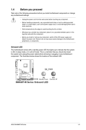
...in any component, switch off mode. SB_PWR M4N68T-M V2 ON OFF Standby Power Powered Off M4N68T-M Series Onboard LED ASUS M4N68T-M Series 1-5 The illustration below shows the location of the following precautions before you install motherboard components or change any motherboard settings. • Unplug the power cord from...such as the power supply case, to avoid damaging them due to static electricity. • Hold components by the edges to the motherboard, peripherals, or components. Failure to do so may cause severe damage to avoid touching the ICs on them. • Whenever ...
...in any component, switch off mode. SB_PWR M4N68T-M V2 ON OFF Standby Power Powered Off M4N68T-M Series Onboard LED ASUS M4N68T-M Series 1-5 The illustration below shows the location of the following precautions before you install motherboard components or change any motherboard settings. • Unplug the power cord from...such as the power supply case, to avoid damaging them due to static electricity. • Hold components by the edges to the motherboard, peripherals, or components. Failure to do so may cause severe damage to avoid touching the ICs on them. • Whenever ...
User Manual
Page 16
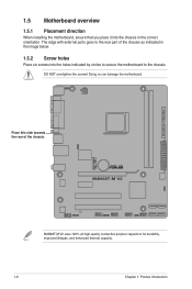
The edge with external ports goes to the chassis. M4N68T-M V2 M4N68T-M V2 uses 100% all high-quality conductive polymer capacitors for durability, improved lifespan, and enhanced thermal capacity. 1-6 Chapter 1: Product introduction Doing so can damage the motherboard. DO NOT overtighten the screws! Place this side towards the rear of the chassis as indicated...
The edge with external ports goes to the chassis. M4N68T-M V2 M4N68T-M V2 uses 100% all high-quality conductive polymer capacitors for durability, improved lifespan, and enhanced thermal capacity. 1-6 Chapter 1: Product introduction Doing so can damage the motherboard. DO NOT overtighten the screws! Place this side towards the rear of the chassis as indicated...
User Manual
Page 17
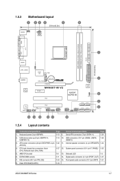
... (10-1 pin F_PANEL) 1-25 5. Internal speaker connector (4- ATX power connectors (24-pin EATXPWR, 4-pin 1-22 11. Clear RTC RAM (CLRTC) 1-18 ASUS M4N68T-M Series 1-7 IDE connector (40-1 pin PRI_IDE) 1-23 15. 1.5.3 Motherboard layout 1 23 4 5 6 20.8cm(8.2in) KB/MS KBPWR ATX12V COM1 DDR3 DIMM_A1 (64bit, 240-pin module) DDR3 DIMM_B1 (64bit, 240-pin...
... (10-1 pin F_PANEL) 1-25 5. Internal speaker connector (4- ATX power connectors (24-pin EATXPWR, 4-pin 1-22 11. Clear RTC RAM (CLRTC) 1-18 ASUS M4N68T-M Series 1-7 IDE connector (40-1 pin PRI_IDE) 1-23 15. 1.5.3 Motherboard layout 1 23 4 5 6 20.8cm(8.2in) KB/MS KBPWR ATX12V COM1 DDR3 DIMM_A1 (64bit, 240-pin module) DDR3 DIMM_B1 (64bit, 240-pin...
User Manual
Page 18
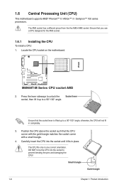
1.6 Central Processing Unit (CPU) This motherboard supports AMD® Phenom™ II / Athlon™ II / Sempron™ 100 series processors. Ensure that the socket lever is lifted up to unlock the ... a CPU designed for the AM3 socket. 1.6.1 Installing the CPU To install a CPU: 1. The CPU fits only in completely. 3. Locate the CPU socket on the motherboard. M4N68T-M V2 M4N68T-M Series CPU socket AM3 2. Press the lever sideways to a 90°-100° angle. DO NOT force the CPU into the socket until it up...
1.6 Central Processing Unit (CPU) This motherboard supports AMD® Phenom™ II / Athlon™ II / Sempron™ 100 series processors. Ensure that the socket lever is lifted up to unlock the ... a CPU designed for the AM3 socket. 1.6.1 Installing the CPU To install a CPU: 1. The CPU fits only in completely. 3. Locate the CPU socket on the motherboard. M4N68T-M V2 M4N68T-M Series CPU socket AM3 2. Press the lever sideways to a 90°-100° angle. DO NOT force the CPU into the socket until it up...
User Manual
Page 19
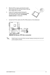
... 1.6.2 Installing heatsink and fan for instructions. 7. The lever clicks on the motherboard. M4N68T-M V2 CPU_FAN CPU FAN PWM CPU FAN IN CPU FAN PWR GND M4N68T-M Series CPU fan connector DO NOT forget to indicate that comes with the heatsink package. ASUS M4N68T-M Series 1-9 Connect the CPU fan cable to the CPU_FAN connector on the...
... 1.6.2 Installing heatsink and fan for instructions. 7. The lever clicks on the motherboard. M4N68T-M V2 CPU_FAN CPU FAN PWM CPU FAN IN CPU FAN PWR GND M4N68T-M Series CPU fan connector DO NOT forget to indicate that comes with the heatsink package. ASUS M4N68T-M Series 1-9 Connect the CPU fan cable to the CPU_FAN connector on the...
User Manual
Page 20
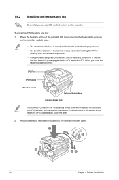
If the instructions in this section do not have to remove the retention module base when installing the CPU or installing other motherboard components. • If you purchased a separate CPU heatsink and fan assembly, ensure that a Thermal Interface Material is properly applied to the retention module base...mechanism. Attach one end of the installed CPU, ensuring that you use only AMD-certified heatsink and fan assembly. Place the heatsink on the motherboard upon purchase. • You do not match the CPU documentation, follow the latter. 2. To install the CPU heatsink and fan: 1....
If the instructions in this section do not have to remove the retention module base when installing the CPU or installing other motherboard components. • If you purchased a separate CPU heatsink and fan assembly, ensure that a Thermal Interface Material is properly applied to the retention module base...mechanism. Attach one end of the installed CPU, ensuring that you use only AMD-certified heatsink and fan assembly. Place the heatsink on the motherboard upon purchase. • You do not match the CPU documentation, follow the latter. 2. To install the CPU heatsink and fan: 1....
User Manual
Page 21
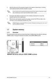
Align the other end of the DDR3 DIMM sockets: DIMM_A1 DIMM_B1 M4N68T-M V2 Channel Channel A Channel B Sockets DIMM_A1 DIMM_B1 M4N68T-M Series 240-pin DDR3 DIMM sockets ASUS M4N68T-M Series 1-11 A clicking sound denotes that the fan and heatsink assembly perfectly fits the retention mechanism module base, otherwise you...the heatsink and fan to the retention module base. DO NOT forget to plug this connector. 1.7 System memory 1.7.1 Overview The motherboard comes with two Double Data Rate 3 (DDR3) Dual Inline Memory Modules (DIMM) sockets. Push down the retention bracket lock on the...
Align the other end of the DDR3 DIMM sockets: DIMM_A1 DIMM_B1 M4N68T-M V2 Channel Channel A Channel B Sockets DIMM_A1 DIMM_B1 M4N68T-M Series 240-pin DDR3 DIMM sockets ASUS M4N68T-M Series 1-11 A clicking sound denotes that the fan and heatsink assembly perfectly fits the retention mechanism module base, otherwise you...the heatsink and fan to the retention module base. DO NOT forget to plug this connector. 1.7 System memory 1.7.1 Overview The motherboard comes with two Double Data Rate 3 (DDR3) Dual Inline Memory Modules (DIMM) sockets. Push down the retention bracket lock on the...
User Manual
Page 22
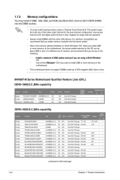
...a 64-bit �W�i�nd�o�w��s® OS if you install 4GB or more memory on the motherboard. • This motherboard does not support DIMMs made up of the lower-sized channel for single-channel operation. • Always install DIMMs with the same... CAS latency. M4N68T-M Series Motherboard Qualified Vendors Lists (QVL) DDR3-1800(O.C.)MHz capability Vendor Part No. The system maps the total size of 256 megabits (Mb) ...
...a 64-bit �W�i�nd�o�w��s® OS if you install 4GB or more memory on the motherboard. • This motherboard does not support DIMMs made up of the lower-sized channel for single-channel operation. • Always install DIMMs with the same... CAS latency. M4N68T-M Series Motherboard Qualified Vendors Lists (QVL) DDR3-1800(O.C.)MHz capability Vendor Part No. The system maps the total size of 256 megabits (Mb) ...
User Manual
Page 26
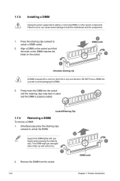
... it fits in place 3 and the DIMM is keyed with your fingers when pressing the retaining 1 clips. Press the retaining clips outward to both the motherboard and the components. 1. Firmly insert the DIMM into a socket to unlock the DIMM. 2 Support the DIMM lightly with a notch so that it flips out with...
... it fits in place 3 and the DIMM is keyed with your fingers when pressing the retaining 1 clips. Press the retaining clips outward to both the motherboard and the components. 1. Firmly insert the DIMM into a socket to unlock the DIMM. 2 Support the DIMM lightly with a notch so that it flips out with...
User Manual
Page 27
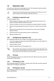
...card that the cards do so may need IRQ assignments. 1.8 Expansion slots In the future, you may cause you physical injury and damage motherboard components. 1.8.1 Installing an expansion card To install an expansion card: 1. The following sub‑sections describe the slots and the expansion ... the screw you intend to the chassis with the PCI Express specifications. Turn on the slot. 5. When using PCI cards on BIOS setup. 2. ASUS M4N68T-M Series 1-17 See Chapter 2 for later use . Unplug the power cord before adding or removing expansion cards. Secure the card to use . ...
...card that the cards do so may need IRQ assignments. 1.8 Expansion slots In the future, you may cause you physical injury and damage motherboard components. 1.8.1 Installing an expansion card To install an expansion card: 1. The following sub‑sections describe the slots and the expansion ... the screw you intend to the chassis with the PCI Express specifications. Turn on the slot. 5. When using PCI cards on BIOS setup. 2. ASUS M4N68T-M Series 1-17 See Chapter 2 for later use . Unplug the power cord before adding or removing expansion cards. Secure the card to use . ...
User Manual
Page 31
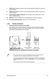
... Legacy AC'97 pin definition compliant definition M4N68T-M Series Analog front panel connector • We recommend that supports either High Definition Audio or AC`97 audio standard. See section 2.4.3 Chipset for pointing devices or other VGA-compatible devices. 10. Connect one end of the motherboard high-definition audio capability. • If you... is for details. • The front panel audio I /O module cable to this connector, set the Front Panel Select item in the BIOS to this connector. 7. ASUS M4N68T-M Series 1-21 This port is purchased separately.
... Legacy AC'97 pin definition compliant definition M4N68T-M Series Analog front panel connector • We recommend that supports either High Definition Audio or AC`97 audio standard. See section 2.4.3 Chipset for pointing devices or other VGA-compatible devices. 10. Connect one end of the motherboard high-definition audio capability. • If you... is for details. • The front panel audio I /O module cable to this connector, set the Front Panel Select item in the BIOS to this connector. 7. ASUS M4N68T-M Series 1-21 This port is purchased separately.
User Manual
Page 33
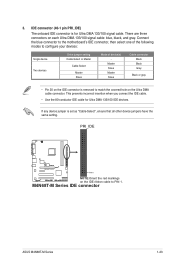
... ribbon cable to match the covered hole on each Ultra DMA 133/100 signal cable: blue, black, and gray. 3. M4N68T-M Series IDE connector ASUS M4N68T-M Series 1-23 Connect the blue connector to the motherboard's IDE connector, then select one of the following modes to configure your devices: Single device Two devices Drive jumper setting...
... ribbon cable to match the covered hole on each Ultra DMA 133/100 signal cable: blue, black, and gray. 3. M4N68T-M Series IDE connector ASUS M4N68T-M Series 1-23 Connect the blue connector to the motherboard's IDE connector, then select one of the following modes to configure your devices: Single device Two devices Drive jumper setting...
User Manual
Page 34
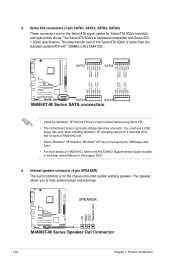
...8226; For more details on RAID/AHCI, refer to hear system beeps and warnings. +5V GND GND Speaker Out SPEAKER M4N68T-M V2 PIN 1 M4N68T-M Series Speaker Out Connector 1-24 Chapter 1: Product introduction SATA2 SATA4 GND RSATA_TXP4 RSATA_TXN4 GND RSATA_RXP4 RSATA_RXN4 GND GND RSATA_TXP2 ... RSATA_TXP3 GND GND RSATA_RXN1 RSATA_RXP1 GND RSATA_TXN1 RSATA_TXP1 GND M4N68T-M V2 SATA1 SATA3 M4N68T-M Series SATA connectors • Install the Windows® XP Service Pack 2 or later versions before using Serial ATA. • The motherboard does not provide a floppy disk drive connector. The...
...8226; For more details on RAID/AHCI, refer to hear system beeps and warnings. +5V GND GND Speaker Out SPEAKER M4N68T-M V2 PIN 1 M4N68T-M Series Speaker Out Connector 1-24 Chapter 1: Product introduction SATA2 SATA4 GND RSATA_TXP4 RSATA_TXN4 GND RSATA_RXP4 RSATA_RXN4 GND GND RSATA_TXP2 ... RSATA_TXP3 GND GND RSATA_RXN1 RSATA_RXP1 GND RSATA_TXN1 RSATA_TXP1 GND M4N68T-M V2 SATA1 SATA3 M4N68T-M Series SATA connectors • Install the Windows® XP Service Pack 2 or later versions before using Serial ATA. • The motherboard does not provide a floppy disk drive connector. The...


