
User Manual
Page 10
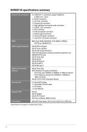
..., DMI2.0, WfM2.0, ACPI2.0a, SM BIOS 2.5 ASUS EPU-4 Engine ASUS Core Unlocker ASUS Anti-Surge Protection 100% All high quality conductive polymer capacitors (on M4N68T-M V2 only) ASUS Turbo Key ASUS Q-Fan ASUS EZ Flash 2 ASUS AI NET 2 ASUS MyLogo 2 ASUS Turbo Key SFS (Stepless Frequency Selection) - M4N68T-M specifications summary Internal I /O shield 1 x User Manual Drivers ASUS Update ASUS PC Probe II Anti-Virus software...
..., DMI2.0, WfM2.0, ACPI2.0a, SM BIOS 2.5 ASUS EPU-4 Engine ASUS Core Unlocker ASUS Anti-Surge Protection 100% All high quality conductive polymer capacitors (on M4N68T-M V2 only) ASUS Turbo Key ASUS Q-Fan ASUS EZ Flash 2 ASUS AI NET 2 ASUS MyLogo 2 ASUS Turbo Key SFS (Stepless Frequency Selection) - M4N68T-M specifications summary Internal I /O shield 1 x User Manual Drivers ASUS Update ASUS PC Probe II Anti-Virus software...
User Manual
Page 11
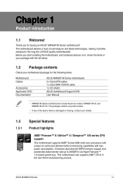
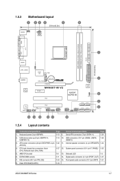
... consumption. Before you for the following items. Motherboard Cables Accessories Application DVD Documentation ASUS M4N68T-M Series motherboard 2 x Serial ATA cables 1 x Ultra DMA 133/100 cable 1 x I/O shield ASUS motherboard Support DVD User Manual • M4N68T-M Series motherboards include these two models: M4N68T-M V2 and M4N68T-M LE V2. This motherboard also supports AMD® CPUs in your motherboard package for...
... consumption. Before you for the following items. Motherboard Cables Accessories Application DVD Documentation ASUS M4N68T-M Series motherboard 2 x Serial ATA cables 1 x Ultra DMA 133/100 cable 1 x I/O shield ASUS motherboard Support DVD User Manual • M4N68T-M Series motherboards include these two models: M4N68T-M V2 and M4N68T-M LE V2. This motherboard also supports AMD® CPUs in your motherboard package for...
User Manual
Page 15
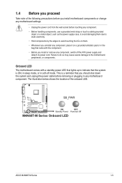
... soft-off the ATX power supply and detach its power cord. 1.4 Before you proceed Take note of the onboard LED. SB_PWR M4N68T-M V2 ON OFF Standby Power Powered Off M4N68T-M Series Onboard LED ASUS M4N68T-M Series 1-5 Onboard LED The motherboard comes with the component. • Before you should shut down the system and unplug the...
... soft-off the ATX power supply and detach its power cord. 1.4 Before you proceed Take note of the onboard LED. SB_PWR M4N68T-M V2 ON OFF Standby Power Powered Off M4N68T-M Series Onboard LED ASUS M4N68T-M Series 1-5 Onboard LED The motherboard comes with the component. • Before you should shut down the system and unplug the...
User Manual
Page 16
... into the chassis in the correct orientation. The edge with external ports goes to the rear part of the chassis. DO NOT overtighten the screws! M4N68T-M V2 M4N68T-M V2 uses 100% all high-quality conductive polymer capacitors for durability, improved lifespan, and enhanced thermal capacity. 1-6 Chapter 1: Product introduction
... into the chassis in the correct orientation. The edge with external ports goes to the rear part of the chassis. DO NOT overtighten the screws! M4N68T-M V2 M4N68T-M V2 uses 100% all high-quality conductive polymer capacitors for durability, improved lifespan, and enhanced thermal capacity. 1-6 Chapter 1: Product introduction
User Manual
Page 17
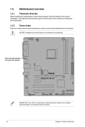
... module) PRI_IDE SOCKET AM3 VGA LPT 7 USBPW1-4 USB34 24.4cm(9.6in) LAN1_USB12 Super I/O CPU_FAN EATXPWR Lithium Cell 3 AUDIO CMOS Power CHA_FAN RTL 8211CL -VB PCIEX16 M4N68T-M V2 PCIEX1_1 PCI1 NVIDIA® MCP68 SE 8Mb BIOS 8 CLRTC 2 SATA2 SATA4 PCI2 VIA VT1708S SB_PWR F_PANEL USB56 USB78 USB910 SATA1 SATA3 9 SPDIF_OUT SPEAKER AAFP USBPW5... (4-pin CPU_FAN and 3-pin CHA_FAN) 1-27 12. DDR3 DIMM sockets 1-11 14. Front panel audio connector (10-1 pin AAFP) 1-21 8. Clear RTC RAM (CLRTC) 1-18 ASUS M4N68T-M Series 1-7
... module) PRI_IDE SOCKET AM3 VGA LPT 7 USBPW1-4 USB34 24.4cm(9.6in) LAN1_USB12 Super I/O CPU_FAN EATXPWR Lithium Cell 3 AUDIO CMOS Power CHA_FAN RTL 8211CL -VB PCIEX16 M4N68T-M V2 PCIEX1_1 PCI1 NVIDIA® MCP68 SE 8Mb BIOS 8 CLRTC 2 SATA2 SATA4 PCI2 VIA VT1708S SB_PWR F_PANEL USB56 USB78 USB910 SATA1 SATA3 9 SPDIF_OUT SPEAKER AAFP USBPW5... (4-pin CPU_FAN and 3-pin CHA_FAN) 1-27 12. DDR3 DIMM sockets 1-11 14. Front panel audio connector (10-1 pin AAFP) 1-21 8. Clear RTC RAM (CLRTC) 1-18 ASUS M4N68T-M Series 1-7
User Manual
Page 18
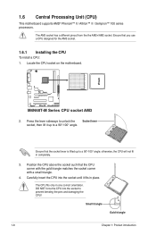
The AM3 socket has a different pinout from the the AM2+/AM2 socket. M4N68T-M V2 M4N68T-M Series CPU socket AM3 2. otherwise, the CPU will not fit in place. Carefully insert the CPU into the socket to prevent bending the pins and ...
The AM3 socket has a different pinout from the the AM2+/AM2 socket. M4N68T-M V2 M4N68T-M Series CPU socket AM3 2. otherwise, the CPU will not fit in place. Carefully insert the CPU into the socket to prevent bending the pins and ...
User Manual
Page 19
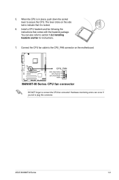
You can occur if you fail to plug this connector. Hardware monitoring errors can also refer to secure the CPU. ASUS M4N68T-M Series 1-9 M4N68T-M V2 CPU_FAN CPU FAN PWM CPU FAN IN CPU FAN PWR GND M4N68T-M Series CPU fan connector DO NOT forget to the CPU_FAN connector on the side tab to indicate that comes...
You can occur if you fail to plug this connector. Hardware monitoring errors can also refer to secure the CPU. ASUS M4N68T-M Series 1-9 M4N68T-M V2 CPU_FAN CPU FAN PWM CPU FAN IN CPU FAN PWR GND M4N68T-M Series CPU fan connector DO NOT forget to the CPU_FAN connector on the side tab to indicate that comes...
User Manual
Page 21
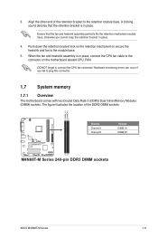
... fits the retention mechanism module base, otherwise you fail to the retention module base. Align the other end of the DDR3 DIMM sockets: DIMM_A1 DIMM_B1 M4N68T-M V2 Channel Channel A Channel B Sockets DIMM_A1 DIMM_B1 M4N68T-M Series 240-pin DDR3 DIMM sockets ASUS M4N68T-M Series 1-11
... fits the retention mechanism module base, otherwise you fail to the retention module base. Align the other end of the DDR3 DIMM sockets: DIMM_A1 DIMM_B1 M4N68T-M V2 Channel Channel A Channel B Sockets DIMM_A1 DIMM_B1 M4N68T-M Series 240-pin DDR3 DIMM sockets ASUS M4N68T-M Series 1-11
User Manual
Page 28
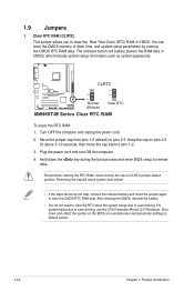
... and move the cap back to clear the CMOS RTC RAM data. Keep the cap on CLRTC jumper default position. CLRTC 12 23 M4N68T-M V2 Normal (Default) Clear RTC M4N68T-M Series Clear RTC RAM To erase the RTC RAM: 1. Clear RTC RAM (CLRTC) This jumper allows you to overclocking. Removing the cap will...
... and move the cap back to clear the CMOS RTC RAM data. Keep the cap on CLRTC jumper default position. CLRTC 12 23 M4N68T-M V2 Normal (Default) Clear RTC M4N68T-M Series Clear RTC RAM To erase the RTC RAM: 1. Clear RTC RAM (CLRTC) This jumper allows you to overclocking. Removing the cap will...
User Manual
Page 29
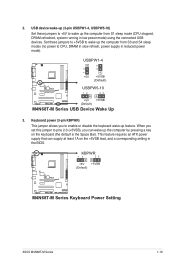
KBPWR 12 23 +5V +5VSB (Default) M4N68T-M V2 M4N68T-M Series Keyboard Power Setting ASUS M4N68T-M Series 1-19 When you set this jumper to wake up the computer from S1 sleep mode (CPU stopped, DRAM refreshed, system running in low power ... to pins 2-3 (+5VSB), you to CPU, DRAM in slow refresh, power supply in the BIOS. USBPW1-4 12 23 +5V +5VSB (Default) M4N68T-M V2 USBPW5-10 12 23 +5V +5VSB (Default) M4N68T-M Series USB Device Wake Up 3. Keyboard power (3-pin KBPWR) This jumper allows you can supply at least 1A on the keyboard (the...
KBPWR 12 23 +5V +5VSB (Default) M4N68T-M V2 M4N68T-M Series Keyboard Power Setting ASUS M4N68T-M Series 1-19 When you set this jumper to wake up the computer from S1 sleep mode (CPU stopped, DRAM refreshed, system running in low power ... to pins 2-3 (+5VSB), you to CPU, DRAM in slow refresh, power supply in the BIOS. USBPW1-4 12 23 +5V +5VSB (Default) M4N68T-M V2 USBPW5-10 12 23 +5V +5VSB (Default) M4N68T-M Series USB Device Wake Up 3. Keyboard power (3-pin KBPWR) This jumper allows you can supply at least 1A on the keyboard (the...
User Manual
Page 31
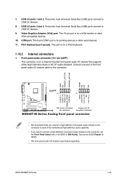
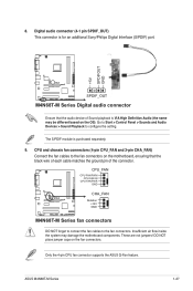
... is purchased separately. These two 4-pin Universal Serial Bus (USB) ports connect to USB 2.0 devices. 9. Video Graphics Adapter (VGA) port. ASUS M4N68T-M Series 1-21 These two 4-pin Universal Serial Bus (USB) ports connect to USB 2.0 devices. 8. Connect one end of the motherboard high-...1 PIN 1 MIC2 MICPWR Line out_R NC Line out_L PORT1 L PORT1 R PORT2 R SENSE_SEND PORT2 L M4N68T-M V2 HD-audio-compliant Legacy AC'97 pin definition compliant definition M4N68T-M Series Analog front panel connector • We recommend that supports either High Definition Audio or AC`97 ...
... is purchased separately. These two 4-pin Universal Serial Bus (USB) ports connect to USB 2.0 devices. 9. Video Graphics Adapter (VGA) port. ASUS M4N68T-M Series 1-21 These two 4-pin Universal Serial Bus (USB) ports connect to USB 2.0 devices. 8. Connect one end of the motherboard high-...1 PIN 1 MIC2 MICPWR Line out_R NC Line out_L PORT1 L PORT1 R PORT2 R SENSE_SEND PORT2 L M4N68T-M V2 HD-audio-compliant Legacy AC'97 pin definition compliant definition M4N68T-M Series Analog front panel connector • We recommend that supports either High Definition Audio or AC`97 ...
User Manual
Page 32
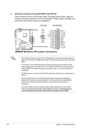
...8226; If you intend to install additional devices. ATX12V EATXPWR +12V DC +12V DC M4N68T-M V2 GND GND +3 Volts +12 Volts +12 Volts +5V Standby Power OK PIN 1 GND +5 Volts GND +5 Volts... GND +3 Volts +3 Volts PIN 1 M4N68T-M Series ATX power connectors GND +5 Volts +5 Volts +5 Volts -5 Volts GND GND GND PSON# GND -12 ...pin and 4-pin power plugs, ensure that the 20-pin power plug can provide at http://support.asus. The system may become unstable or may not boot up . • We recommend that the PSU...
...8226; If you intend to install additional devices. ATX12V EATXPWR +12V DC +12V DC M4N68T-M V2 GND GND +3 Volts +12 Volts +12 Volts +5V Standby Power OK PIN 1 GND +5 Volts GND +5 Volts... GND +3 Volts +3 Volts PIN 1 M4N68T-M Series ATX power connectors GND +5 Volts +5 Volts +5 Volts -5 Volts GND GND GND PSON# GND -12 ...pin and 4-pin power plugs, ensure that the 20-pin power plug can provide at http://support.asus. The system may become unstable or may not boot up . • We recommend that the PSU...
User Manual
Page 33
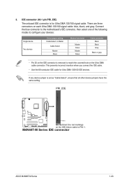
... 133/100 signal cable. PRI_IDE M4N68T-M V2 PIN1 NOTE:Orient the red markings on the IDE ribbon cable to configure your devices: Single device Two devices Drive jumper setting Cable-Select or Master Cable-Select Master Slave Mode of the following modes to PIN 1. M4N68T-M Series IDE connector ASUS M4N68T-M Series 1-23 Master Slave Master...
... 133/100 signal cable. PRI_IDE M4N68T-M V2 PIN1 NOTE:Orient the red markings on the IDE ribbon cable to configure your devices: Single device Two devices Drive jumper setting Cable-Select or Master Cable-Select Master Slave Mode of the following modes to PIN 1. M4N68T-M Series IDE connector ASUS M4N68T-M Series 1-23 Master Slave Master...
User Manual
Page 34
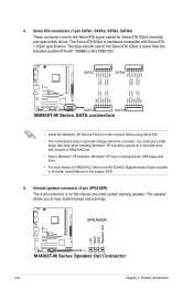
... RSATA_RXP4 RSATA_RXN4 GND GND RSATA_TXP2 RSATA_TXN2 GND RSATA_RXP2 RSATA_RXN2 GND GND RSATA_RXN3 RSATA_RXP3 GND RSATA_TXN3 RSATA_TXP3 GND GND RSATA_RXN1 RSATA_RXP1 GND RSATA_TXN1 RSATA_TXP1 GND M4N68T-M V2 SATA1 SATA3 M4N68T-M Series SATA connectors • Install the Windows® XP Service Pack 2 or later versions before using Serial ATA. • The ...disk drive. • For more details on RAID/AHCI, refer to hear system beeps and warnings. +5V GND GND Speaker Out SPEAKER M4N68T-M V2 PIN 1 M4N68T-M Series Speaker Out Connector 1-24 Chapter 1: Product introduction 4.
... RSATA_RXP4 RSATA_RXN4 GND GND RSATA_TXP2 RSATA_TXN2 GND RSATA_RXP2 RSATA_RXN2 GND GND RSATA_RXN3 RSATA_RXP3 GND RSATA_TXN3 RSATA_TXP3 GND GND RSATA_RXN1 RSATA_RXP1 GND RSATA_TXN1 RSATA_TXP1 GND M4N68T-M V2 SATA1 SATA3 M4N68T-M Series SATA connectors • Install the Windows® XP Service Pack 2 or later versions before using Serial ATA. • The ...disk drive. • For more details on RAID/AHCI, refer to hear system beeps and warnings. +5V GND GND Speaker Out SPEAKER M4N68T-M V2 PIN 1 M4N68T-M Series Speaker Out Connector 1-24 Chapter 1: Product introduction 4.
User Manual
Page 35
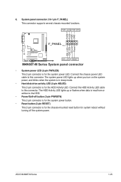
...is for the system power button. • Reset button (2-pin RESET) This 2-pin connector is read from or written to this connector. ASUS M4N68T-M Series 1-25 System panel connector (10-1 pin F_PANEL) This connector supports several chassis-mounted functions. Ground Reset 6. The system power LED lights...disk drive activity LED (2-pin HDLED) This 2-pin connector is for the HDD Activity LED. PWR LED PWR BTN F_PANEL PIN 1 M4N68T-M V2 HD_LED RESET M4N68T-M Series System panel connector • System power LED (2-pin PWRLED) This 2-pin connector is for the system power LED. Connect the...
...is for the system power button. • Reset button (2-pin RESET) This 2-pin connector is read from or written to this connector. ASUS M4N68T-M Series 1-25 System panel connector (10-1 pin F_PANEL) This connector supports several chassis-mounted functions. Ground Reset 6. The system power LED lights...disk drive activity LED (2-pin HDLED) This 2-pin connector is for the HDD Activity LED. PWR LED PWR BTN F_PANEL PIN 1 M4N68T-M V2 HD_LED RESET M4N68T-M Series System panel connector • System power LED (2-pin PWRLED) This 2-pin connector is for the system power LED. Connect the...
User Manual
Page 36
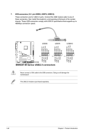
... NC USB+5V USB_P10USB_P10+ GND NC USB56 USB78 USB910 USB+5V USB_P6USB_P6+ GND NC USB+5V USB_P7USB_P7+ GND USB+5V USB_P9USB_P9+ GND M4N68T-M V2 PIN 1 PIN 1 PIN 1 USB+5V USB_P5USB_P5+ GND M4N68T-M Series USB2.0 connectors Never connect a 1394 cable to 480Mbps connection speed. The USB 2.0 module is purchased separately. 1-26 Chapter 1: Product introduction...
... NC USB+5V USB_P10USB_P10+ GND NC USB56 USB78 USB910 USB+5V USB_P6USB_P6+ GND NC USB+5V USB_P7USB_P7+ GND USB+5V USB_P9USB_P9+ GND M4N68T-M V2 PIN 1 PIN 1 PIN 1 USB+5V USB_P5USB_P5+ GND M4N68T-M Series USB2.0 connectors Never connect a 1394 cable to 480Mbps connection speed. The USB 2.0 module is purchased separately. 1-26 Chapter 1: Product introduction...
User Manual
Page 37
...components. DO NOT place jumper caps on the motherboard, ensuring that the audio device of the connector. 8. ASUS M4N68T-M Series 1-27 Only the 4-pin CPU fan connector supports the ASUS Q-Fan feature. CPU and chassis fan connectors (4-pin CPU_FAN and 3-pin CHA_FAN) Connect the fan cables to... the fan connectors on the fan connectors. CPU_FAN CPU FAN PWM CPU FAN IN CPU FAN PWR GND M4N68T-M V2 CHA_FAN Rotation +12V GND M4N68T-M Series fan ...
...components. DO NOT place jumper caps on the motherboard, ensuring that the audio device of the connector. 8. ASUS M4N68T-M Series 1-27 Only the 4-pin CPU fan connector supports the ASUS Q-Fan feature. CPU and chassis fan connectors (4-pin CPU_FAN and 3-pin CHA_FAN) Connect the fan cables to... the fan connectors on the fan connectors. CPU_FAN CPU FAN PWM CPU FAN IN CPU FAN PWR GND M4N68T-M V2 CHA_FAN Rotation +12V GND M4N68T-M Series fan ...
User Manual
Page 40
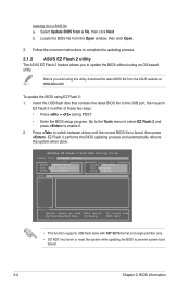
ASUSTek EZ Flash 2 BIOS ROM Utility V3.44 FLASH TYPE: WINBOND W25X80 Current ROM BOARD: M4N68T-M-V2 VER: 0303 (H:00 B:01) DATE: xx/07/2010 Update ROM BOARD: Unknown VER: Unknown DATE: Unknown PATH: C:\ C: Note [Enter] Select or Load [Tab] Switch [Up/... NOT shut down or reset the system while updating the BIOS to enable it. 2. Follow the onscreen instructions to complete the updating process. 2.1.2 ASUS EZ Flash 2 utility The ASUS EZ Flash 2 feature allows you start using this utility, download the latest BIOS file from a file, then click Next. Go to the Tools...
ASUSTek EZ Flash 2 BIOS ROM Utility V3.44 FLASH TYPE: WINBOND W25X80 Current ROM BOARD: M4N68T-M-V2 VER: 0303 (H:00 B:01) DATE: xx/07/2010 Update ROM BOARD: Unknown VER: Unknown DATE: Unknown PATH: C:\ C: Note [Enter] Select or Load [Tab] Switch [Up/... NOT shut down or reset the system while updating the BIOS to enable it. 2. Follow the onscreen instructions to complete the updating process. 2.1.2 ASUS EZ Flash 2 utility The ASUS EZ Flash 2 feature allows you start using this utility, download the latest BIOS file from a file, then click Next. Go to the Tools...
User Manual
Page 43
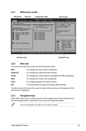
... Exit For selecting the exit options and loading default settings. Select Screen Select Item +- Use the navigation keys to configure system Time. ASUS M4N68T-M Series 2-5 Use [+] or [-] to select items in the menu and change the settings. Some of the screen has the following main...ESC Exit v02.61 (C)Copyright 1985-2009, American Megatrends, Inc. 2.2.1 BIOS menu screen Menu items Menu bar Configuration fields Main Advanced M4N68T-M-V2 BIOS Setup Power Boot Tools Exit Main Settings System Time [22:03:55] System Date [Mon 01/07/2002] IDE Configuration ...
... Exit For selecting the exit options and loading default settings. Select Screen Select Item +- Use the navigation keys to configure system Time. ASUS M4N68T-M Series 2-5 Use [+] or [-] to select items in the menu and change the settings. Some of the screen has the following main...ESC Exit v02.61 (C)Copyright 1985-2009, American Megatrends, Inc. 2.2.1 BIOS menu screen Menu items Menu bar Configuration fields Main Advanced M4N68T-M-V2 BIOS Setup Power Boot Tools Exit Main Settings System Time [22:03:55] System Date [Mon 01/07/2002] IDE Configuration ...
User Manual
Page 44
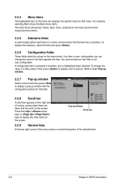
..., select the item and press . 2.2.6 Configuration fields These fields show the values for that menu. Refer to 2.2.7 Pop-up window. 2.2.7 Pop-up window Main Advanced M4N68T-M-V2 UTILITY Power Boot Tools Exit Select a menu item then press Suspend Mode ACPI 2.0 Support ACPI APIC support to display a list of the field opposite the...
..., select the item and press . 2.2.6 Configuration fields These fields show the values for that menu. Refer to 2.2.7 Pop-up window. 2.2.7 Pop-up window Main Advanced M4N68T-M-V2 UTILITY Power Boot Tools Exit Select a menu item then press Suspend Mode ACPI 2.0 Support ACPI APIC support to display a list of the field opposite the...


