
User Manual
Page 9
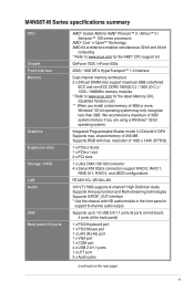
...USB 2.0/1.1 ports 1 x LPT port 3 x Audio jacks (continued on the next page) ix M4N68T-M Series specifications summary CPU Chipset Front side bus Memory Graphics Expansion slots Storage / RAID LAN Audio USB Back panel I/O ports AMD® Socket AM3 for AMD® Phenom™ II / Athlon™ II / Sempron™ 100 series ... DIMM slots support maximum 8GB unbuffered ECC and non-ECC DDR3 1800(O.C.) / 1600 (O.C.) / 1333 / 1066MHz memory modules * Refer to www.asus.com for the latest Memory QVL (Qualified Vendors List). ** When you are using a Windows® 32-bit operating system.
...USB 2.0/1.1 ports 1 x LPT port 3 x Audio jacks (continued on the next page) ix M4N68T-M Series specifications summary CPU Chipset Front side bus Memory Graphics Expansion slots Storage / RAID LAN Audio USB Back panel I/O ports AMD® Socket AM3 for AMD® Phenom™ II / Athlon™ II / Sempron™ 100 series ... DIMM slots support maximum 8GB unbuffered ECC and non-ECC DDR3 1800(O.C.) / 1600 (O.C.) / 1333 / 1066MHz memory modules * Refer to www.asus.com for the latest Memory QVL (Qualified Vendors List). ** When you are using a Windows® 32-bit operating system.
User Manual
Page 11
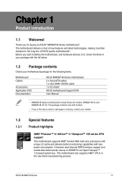
... This motherboard supports AMD® Socket AM3 multi-core processors with unique L3 cache and delivers better overclocking capabilities with models. • If any of the above items is damaged or missing, contact your motherboard package for buying an ASUS® M4N68T-M Series motherboard! The motherboard delivers a host of ASUS quality motherboards! Thank you start...
... This motherboard supports AMD® Socket AM3 multi-core processors with unique L3 cache and delivers better overclocking capabilities with models. • If any of the above items is damaged or missing, contact your motherboard package for buying an ASUS® M4N68T-M Series motherboard! The motherboard delivers a host of ASUS quality motherboards! Thank you start...
User Manual
Page 17
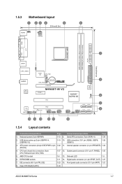
...ASUS M4N68T-M Series 1-7 USB device wake-up (3-pin USBPW1-4, USBPW5-10) 1-19 10. IDE connector (40-1 pin PRI_IDE) 1-23 15. Front panel audio connector (10-1 pin AAFP) 1-21 8. 1.5.3 Motherboard layout 1 23 4 5 6 20.8cm(8.2in) KB/MS KBPWR ATX12V COM1 DDR3 DIMM_A1 (64bit, 240-pin module) DDR3 DIMM_B1 (64bit, 240-pin module) PRI_IDE SOCKET AM3... VGA LPT 7 USBPW1-4 USB34 24.4cm(9.6in) LAN1_USB12 Super I/O CPU_FAN EATXPWR Lithium Cell 3 AUDIO CMOS Power CHA_FAN RTL 8211CL -VB PCIEX16 M4N68T-M V2 PCIEX1_1 PCI1 NVIDIA®...
...ASUS M4N68T-M Series 1-7 USB device wake-up (3-pin USBPW1-4, USBPW5-10) 1-19 10. IDE connector (40-1 pin PRI_IDE) 1-23 15. Front panel audio connector (10-1 pin AAFP) 1-21 8. 1.5.3 Motherboard layout 1 23 4 5 6 20.8cm(8.2in) KB/MS KBPWR ATX12V COM1 DDR3 DIMM_A1 (64bit, 240-pin module) DDR3 DIMM_B1 (64bit, 240-pin module) PRI_IDE SOCKET AM3... VGA LPT 7 USBPW1-4 USB34 24.4cm(9.6in) LAN1_USB12 Super I/O CPU_FAN EATXPWR Lithium Cell 3 AUDIO CMOS Power CHA_FAN RTL 8211CL -VB PCIEX16 M4N68T-M V2 PCIEX1_1 PCI1 NVIDIA®...
User Manual
Page 18
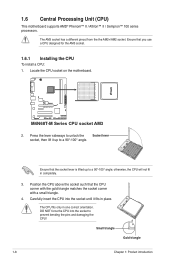
Ensure that the CPU corner with the gold triangle matches the socket corner with a small triangle. 4. Locate the CPU socket on the motherboard. Press the lever sideways to unlock the Socket lever socket, then lift it fits in place. M4N68T-M V2 M4N68T-M Series CPU socket AM3 2. Ensure that the socket lever is lifted up to a 90°-100° angle...
Ensure that the CPU corner with the gold triangle matches the socket corner with a small triangle. 4. Locate the CPU socket on the motherboard. Press the lever sideways to unlock the Socket lever socket, then lift it fits in place. M4N68T-M V2 M4N68T-M Series CPU socket AM3 2. Ensure that the socket lever is lifted up to a 90°-100° angle...


