
User Manual
Page 6
...Canadian Department of parts and recycling. Canadian Department of Communications Statement This digital apparatus does not exceed the Class B limits for connection of shielded cables for radio noise emissions from that may cause harmful interference to enable proper reuse of Communications. DO NOT ...that the battery should not be placed in municipal waste. DO NOT throw the motherboard in our products at ASUS REACH website at http://csr.asus.com/english/REACH.htm. Notices Federal Communications Commission Statement This device complies with Canadian ICES-003. Operation is...
...Canadian Department of parts and recycling. Canadian Department of Communications Statement This digital apparatus does not exceed the Class B limits for connection of shielded cables for radio noise emissions from that may cause harmful interference to enable proper reuse of Communications. DO NOT ...that the battery should not be placed in municipal waste. DO NOT throw the motherboard in our products at ASUS REACH website at http://csr.asus.com/english/REACH.htm. Notices Federal Communications Commission Statement This device complies with Canadian ICES-003. Operation is...
User Manual
Page 7
...before you need when installing and configuring the motherboard. How this guide This user guide contains the information you add a device. • Before connecting or removing signal cables from the motherboard, ensure that your power supply is broken, do not try to the correct voltage in any damage,... and the new technology it by yourself. These devices could interrupt the grounding circuit. • Ensure that all cables are correctly connected and the power cables are using the product, ensure that the power cables for the devices are unplugged before the signal cables are...
...before you need when installing and configuring the motherboard. How this guide This user guide contains the information you add a device. • Before connecting or removing signal cables from the motherboard, ensure that your power supply is broken, do not try to the correct voltage in any damage,... and the new technology it by yourself. These devices could interrupt the grounding circuit. • Ensure that all cables are correctly connected and the power cables are using the product, ensure that the power cables for the devices are unplugged before the signal cables are...
User Manual
Page 12
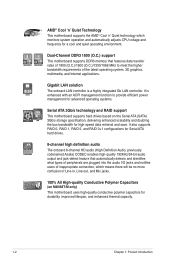
... memory that automatically detects and identifies what types of peripherals are plugged into the audio I/O jacks and notifies users of inappropriate connection, which monitors system operation and automatically adjusts CPU voltage and frequency for durability, improved lifespan, and enhanced thermal capacity. 1-2 ...for advanced operating systems. Serial ATA 3Gb/s technology and RAID support This motherboard supports hard drives based on M4N68T-M only) This motherboard uses high-quality conductive polymer capacitors for a cool and quiet operating environment. It is a highly integrated Gb...
... memory that automatically detects and identifies what types of peripherals are plugged into the audio I/O jacks and notifies users of inappropriate connection, which monitors system operation and automatically adjusts CPU voltage and frequency for durability, improved lifespan, and enhanced thermal capacity. 1-2 ...for advanced operating systems. Serial ATA 3Gb/s technology and RAID support This motherboard supports hard drives based on M4N68T-M only) This motherboard uses high-quality conductive polymer capacitors for a cool and quiet operating environment. It is a highly integrated Gb...
User Manual
Page 14
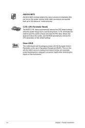
...Union's Restriction on the environment. 1-4 Chapter 1: Product introduction eliminates the need to their default settings. C.P.R. Green ASUS This motherboard and its packaging comply with the ASUS vision of creating environment-friendly and recyclable products/packaging to safeguard consumers' health while minimizing the impact on the ...(RoHS). feature automatically restores the CPU default settings when the system hangs due to 100 meters at 1 meter accuracy. ASUS AI NET2 ASUS AI NET2 remotely detects the cable connection immediately after you turn on the system and any faulty cable...
...Union's Restriction on the environment. 1-4 Chapter 1: Product introduction eliminates the need to their default settings. C.P.R. Green ASUS This motherboard and its packaging comply with the ASUS vision of creating environment-friendly and recyclable products/packaging to safeguard consumers' health while minimizing the impact on the ...(RoHS). feature automatically restores the CPU default settings when the system hangs due to 100 meters at 1 meter accuracy. ASUS AI NET2 ASUS AI NET2 remotely detects the cable connection immediately after you turn on the system and any faulty cable...
User Manual
Page 19
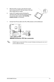
... following the instructions that it is in place, push down the socket lever to connect the CPU fan connector! ASUS M4N68T-M Series 1-9 M4N68T-M V2 CPU_FAN CPU FAN PWM CPU FAN IN CPU FAN PWR GND M4N68T-M Series CPU fan connector DO NOT forget to secure the CPU. When the CPU... is locked. 6. Connect the CPU fan cable to section 1.6.2 Installing heatsink and fan for instructions. 7. ...
... following the instructions that it is in place, push down the socket lever to connect the CPU fan connector! ASUS M4N68T-M Series 1-9 M4N68T-M V2 CPU_FAN CPU FAN PWM CPU FAN IN CPU FAN PWR GND M4N68T-M Series CPU fan connector DO NOT forget to secure the CPU. When the CPU... is locked. 6. Connect the CPU fan cable to section 1.6.2 Installing heatsink and fan for instructions. 7. ...
User Manual
Page 21
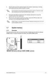
... the retention mechanism module base, otherwise you fail to the module base. 5. When the fan and heatsink assembly is in place, connect the CPU fan cable to the connector on the retention mechanism to secure the heatsink and fan to plug this connector. 1.7 System ... is in place. The figure illustrates the location of the retention bracket to connect the CPU fan connector! 3. Align the other end of the DDR3 DIMM sockets: DIMM_A1 DIMM_B1 M4N68T-M V2 Channel Channel A Channel B Sockets DIMM_A1 DIMM_B1 M4N68T-M Series 240-pin DDR3 DIMM sockets ASUS M4N68T-M Series 1-11
... the retention mechanism module base, otherwise you fail to the module base. 5. When the fan and heatsink assembly is in place, connect the CPU fan cable to the connector on the retention mechanism to secure the heatsink and fan to plug this connector. 1.7 System ... is in place. The figure illustrates the location of the retention bracket to connect the CPU fan connector! 3. Align the other end of the DDR3 DIMM sockets: DIMM_A1 DIMM_B1 M4N68T-M V2 Channel Channel A Channel B Sockets DIMM_A1 DIMM_B1 M4N68T-M Series 240-pin DDR3 DIMM sockets ASUS M4N68T-M Series 1-11
User Manual
Page 29
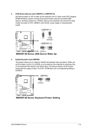
KBPWR 12 23 +5V +5VSB (Default) M4N68T-M V2 M4N68T-M Series Keyboard Power Setting ASUS M4N68T-M Series 1-19 USBPW1-4 12 23 +5V +5VSB (Default) M4N68T-M V2 USBPW5-10 12 23 +5V +5VSB (Default) M4N68T-M Series USB Device Wake Up 3. Set these jumpers to +5V to wake up the computer from S3 and S4 sleep...+5VSB to wake up the computer by pressing a key on the +5VSB lead, and a corresponding setting in low power mode) using the connected USB devices. This feature requires an ATX power supply that can wake up the computer from S1 sleep mode (CPU stopped, DRAM refreshed, system...
KBPWR 12 23 +5V +5VSB (Default) M4N68T-M V2 M4N68T-M Series Keyboard Power Setting ASUS M4N68T-M Series 1-19 USBPW1-4 12 23 +5V +5VSB (Default) M4N68T-M V2 USBPW5-10 12 23 +5V +5VSB (Default) M4N68T-M Series USB Device Wake Up 3. Set these jumpers to +5V to wake up the computer from S3 and S4 sleep...+5VSB to wake up the computer by pressing a key on the +5VSB lead, and a corresponding setting in low power mode) using the connected USB devices. This feature requires an ATX power supply that can wake up the computer from S1 sleep mode (CPU stopped, DRAM refreshed, system...

User Manual
Page 30
...Activity/Link LED Status Description OFF No link ORANGE Linked BLINKING Data activity Speed LED Status OFF ORANGE GREEN Description 10Mbps connection 100Mbps connection 1Gbps connection ACT/LINK SPEED LED LED LAN port 4. Line Out port (lime). Audio 2, 4, 6, 8-channel configuration Port Light... configurations, the function of the audio ports in the front panel to a microphone. LAN (RJ-45) port. This port allows Gigabit connection to a headphone or a speaker. Microphone port (pink). 1.10 1.10.1 Connectors Rear panel ports 1 2 3 45 11 10 9 8 7 6 1....
...Activity/Link LED Status Description OFF No link ORANGE Linked BLINKING Data activity Speed LED Status OFF ORANGE GREEN Description 10Mbps connection 100Mbps connection 1Gbps connection ACT/LINK SPEED LED LED LAN port 4. Line Out port (lime). Audio 2, 4, 6, 8-channel configuration Port Light... configurations, the function of the audio ports in the front panel to a microphone. LAN (RJ-45) port. This port allows Gigabit connection to a headphone or a speaker. Microphone port (pink). 1.10 1.10.1 Connectors Rear panel ports 1 2 3 45 11 10 9 8 7 6 1....
User Manual
Page 31
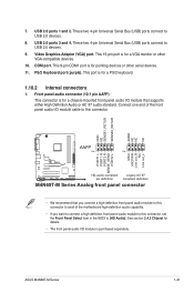
... front panel audio I /O module is for a PS/2 keyboard. 1.10.2 Internal connectors 1. ASUS M4N68T-M Series 1-21 7. COM port. This port is for details. • The front panel audio I /O module cable to [HD Audio]. These two 4-pin Universal Serial Bus (USB) ports connect to USB 2.0 devices. 8. This 15-pin port is purchased separately. See section...
... front panel audio I /O module is for a PS/2 keyboard. 1.10.2 Internal connectors 1. ASUS M4N68T-M Series 1-21 7. COM port. This port is for details. • The front panel audio I /O module cable to [HD Audio]. These two 4-pin Universal Serial Bus (USB) ports connect to USB 2.0 devices. 8. This 15-pin port is purchased separately. See section...
User Manual
Page 32
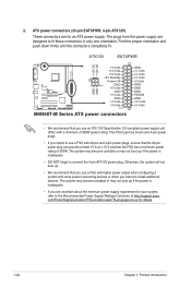
... proper orientation and push down firmly until the connectors completely fit. ATX12V EATXPWR +12V DC +12V DC M4N68T-M V2 GND GND +3 Volts +12 Volts +12 Volts +5V Standby Power OK PIN 1 GND +5 Volts GND +5 Volts...with 20-pin and 4-pin power plugs, ensure that the 20-pin power plug can provide at http://support.asus. com/PowerSupplyCalculator/PSCalculator.aspx?SLanguage=en-us for your system, refer to install additional devices. The system may ...2. ATX power connectors (24-pin EATXPWR, 4-pin ATX12V) These connectors are designed to connect the 4-pin ATX12V power plug.
... proper orientation and push down firmly until the connectors completely fit. ATX12V EATXPWR +12V DC +12V DC M4N68T-M V2 GND GND +3 Volts +12 Volts +12 Volts +5V Standby Power OK PIN 1 GND +5 Volts GND +5 Volts...with 20-pin and 4-pin power plugs, ensure that the 20-pin power plug can provide at http://support.asus. com/PowerSupplyCalculator/PSCalculator.aspx?SLanguage=en-us for your system, refer to install additional devices. The system may ...2. ATX power connectors (24-pin EATXPWR, 4-pin ATX12V) These connectors are designed to connect the 4-pin ATX12V power plug.
User Manual
Page 33
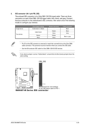
...onboard IDE connector is set as "Cable-Select", ensure that all other device jumpers have the same setting. M4N68T-M Series IDE connector ASUS M4N68T-M Series 1-23 This prevents incorrect insertion when you connect the IDE cable. • Use the 80-conductor IDE cable for Ultra DMA 133/100 signal cable. ...hole on each Ultra DMA 133/100 signal cable: blue, black, and gray. Connect the blue connector to the motherboard's IDE connector, then select one of the following modes to PIN 1. PRI_IDE M4N68T-M V2 PIN1 NOTE:Orient the red markings on the IDE ribbon cable to configure your...
...onboard IDE connector is set as "Cable-Select", ensure that all other device jumpers have the same setting. M4N68T-M Series IDE connector ASUS M4N68T-M Series 1-23 This prevents incorrect insertion when you connect the IDE cable. • Use the 80-conductor IDE cable for Ultra DMA 133/100 signal cable. ...hole on each Ultra DMA 133/100 signal cable: blue, black, and gray. Connect the blue connector to the motherboard's IDE connector, then select one of the following modes to PIN 1. PRI_IDE M4N68T-M V2 PIN1 NOTE:Orient the red markings on the IDE ribbon cable to configure your...
User Manual
Page 35
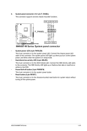
... Activity LED cable to this connector. Connect the chassis power LED cable to the HDD. • Power/Soft-off the system power. The system power LED lights up or flashes when data ... system power button. • Reset button (2-pin RESET) This 2-pin connector is for the system power LED. ASUS M4N68T-M Series 1-25 PLED+ PLEDPWR GND IDE_LED+ IDE_LED- PWR LED PWR BTN F_PANEL PIN 1 M4N68T-M V2 HD_LED RESET M4N68T-M Series System panel connector • System power LED (2-pin PWRLED) This 2-pin connector is for the HDD...
... Activity LED cable to this connector. Connect the chassis power LED cable to the HDD. • Power/Soft-off the system power. The system power LED lights up or flashes when data ... system power button. • Reset button (2-pin RESET) This 2-pin connector is for the system power LED. ASUS M4N68T-M Series 1-25 PLED+ PLEDPWR GND IDE_LED+ IDE_LED- PWR LED PWR BTN F_PANEL PIN 1 M4N68T-M V2 HD_LED RESET M4N68T-M Series System panel connector • System power LED (2-pin PWRLED) This 2-pin connector is for the HDD...
User Manual
Page 36
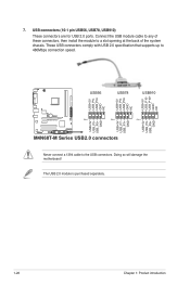
... NC USB56 USB78 USB910 USB+5V USB_P6USB_P6+ GND NC USB+5V USB_P7USB_P7+ GND USB+5V USB_P9USB_P9+ GND M4N68T-M V2 PIN 1 PIN 1 PIN 1 USB+5V USB_P5USB_P5+ GND M4N68T-M Series USB2.0 connectors Never connect a 1394 cable to 480Mbps connection speed. 7. Connect the USB module cable to any of these connectors, then install the module to a slot opening...
... NC USB56 USB78 USB910 USB+5V USB_P6USB_P6+ GND NC USB+5V USB_P7USB_P7+ GND USB+5V USB_P9USB_P9+ GND M4N68T-M V2 PIN 1 PIN 1 PIN 1 USB+5V USB_P5USB_P5+ GND M4N68T-M Series USB2.0 connectors Never connect a 1394 cable to 480Mbps connection speed. 7. Connect the USB module cable to any of these connectors, then install the module to a slot opening...
User Manual
Page 37
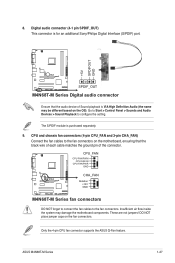
... fan connectors on the OS). CPU_FAN CPU FAN PWM CPU FAN IN CPU FAN PWR GND M4N68T-M V2 CHA_FAN Rotation +12V GND M4N68T-M Series fan connectors DO NOT forget to connect the fan cables to configure the setting. 8. Insufficient air flow inside the system may be... Sony/Philips Digital Interface (S/PDIF) port. +5V SPDIFOUT GND M4N68T-M V2 SPDIF_OUT M4N68T-M Series Digital audio connector Ensure that the black wire of each cable matches the ground pin of Sound playback is purchased separately. 9. ASUS M4N68T-M Series 1-27 The S/PDIF module is VIA High Definition Audio...
... fan connectors on the OS). CPU_FAN CPU FAN PWM CPU FAN IN CPU FAN PWR GND M4N68T-M V2 CHA_FAN Rotation +12V GND M4N68T-M Series fan connectors DO NOT forget to connect the fan cables to configure the setting. 8. Insufficient air flow inside the system may be... Sony/Philips Digital Interface (S/PDIF) port. +5V SPDIFOUT GND M4N68T-M V2 SPDIF_OUT M4N68T-M Series Digital audio connector Ensure that the black wire of each cable matches the ground pin of Sound playback is purchased separately. 9. ASUS M4N68T-M Series 1-27 The S/PDIF module is VIA High Definition Audio...
User Manual
Page 39
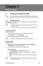
... the dropdown list, select either through the Internet. Select the ASUS FTP site nearest you to manage, save, and update the motherboard BIOS in Windows® environment. • ASUS Update requires an Internet connection either of updating itself through a network or an Internet Service... original motherboard BIOS using this utility. Click the Utilities tab, then click ASUS Update. 3. From the Windows® desktop, click Start > Programs > ASUS > ASUS Update > ASUS Update to download then click Next. ASUS M4N68T-M Series 2-1 From the FTP site, select the BIOS version that you...
... the dropdown list, select either through the Internet. Select the ASUS FTP site nearest you to manage, save, and update the motherboard BIOS in Windows® environment. • ASUS Update requires an Internet connection either of updating itself through a network or an Internet Service... original motherboard BIOS using this utility. Click the Utilities tab, then click ASUS Update. 3. From the Windows® desktop, click Start > Programs > ASUS > ASUS Update > ASUS Update to download then click Next. ASUS M4N68T-M Series 2-1 From the FTP site, select the BIOS version that you...
User Manual
Page 55
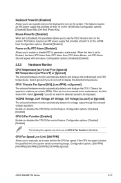
...Function [Enabled] Enables or disables the CPU Q-Fan control feature. Configuration options: [500 RPM] [400 RPM] [300 RPM] [200 RPM] [100 RPM] [Ignored] ASUS M4N68T-M Series 2-17 Configuration options: [Disabled] [Space Bar] [Ctrl-Esc] [Power Key] Mouse PowerOn [Disabled] When set CPU Q-Fan Function to turn on the system.... an ATX power supply that provides at least 1A on By RTC Alarm [Disabled] Allows you set to [Enabled], this item is not connected to generate a wake event. Select [gnored] if you to use specific keys on the keyboard to [Enabled]. This feature requires an ATX...
...Function [Enabled] Enables or disables the CPU Q-Fan control feature. Configuration options: [500 RPM] [400 RPM] [300 RPM] [200 RPM] [100 RPM] [Ignored] ASUS M4N68T-M Series 2-17 Configuration options: [Disabled] [Space Bar] [Ctrl-Esc] [Power Key] Mouse PowerOn [Disabled] When set CPU Q-Fan Function to turn on the system.... an ATX power supply that provides at least 1A on By RTC Alarm [Disabled] Allows you set to [Enabled], this item is not connected to generate a wake event. Select [gnored] if you to use specific keys on the keyboard to [Enabled]. This feature requires an ATX...


