
User Manual
Page 10
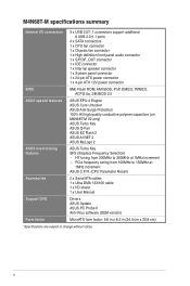
... panel connector 1 x 24-pin ATX power connector 1 x 4-pin ATX 12V power connector BIOS ASUS special features ASUS overclocking features 8Mb Flash ROM, AMI BIOS, PnP, DMI2.0, WfM2.0, ACPI2.0a, SM BIOS 2.5 ASUS EPU-4 Engine ASUS Core Unlocker ASUS Anti-Surge Protection 100% All high quality conductive polymer capacitors (on M4N68T-M V2 only) ASUS Turbo Key ASUS Q-Fan ASUS EZ Flash 2 ASUS AI...
... panel connector 1 x 24-pin ATX power connector 1 x 4-pin ATX 12V power connector BIOS ASUS special features ASUS overclocking features 8Mb Flash ROM, AMI BIOS, PnP, DMI2.0, WfM2.0, ACPI2.0a, SM BIOS 2.5 ASUS EPU-4 Engine ASUS Core Unlocker ASUS Anti-Surge Protection 100% All high quality conductive polymer capacitors (on M4N68T-M V2 only) ASUS Turbo Key ASUS Q-Fan ASUS EZ Flash 2 ASUS AI...
User Manual
Page 17
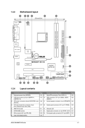
...LED 1-5 6. IDE connector (40-1 pin PRI_IDE) 1-23 15. Clear RTC RAM (CLRTC) 1-18 ASUS M4N68T-M Series 1-7 USB device wake-up (3-pin USBPW1-4, USBPW5-10) 1-19 10. Internal speaker connector (4- System panel connector (10-1 pin F_PANEL) 1-25 5. 1.5.3 Motherboard layout 1 23 4 5 6 20.8cm(8.2in)...USBPW1-4 USB34 24.4cm(9.6in) LAN1_USB12 Super I/O CPU_FAN EATXPWR Lithium Cell 3 AUDIO CMOS Power CHA_FAN RTL 8211CL -VB PCIEX16 M4N68T-M V2 PCIEX1_1 PCI1 NVIDIA® MCP68 SE 8Mb BIOS 8 CLRTC 2 SATA2 SATA4 PCI2 VIA VT1708S SB_PWR F_PANEL USB56 USB78 USB910 SATA1...
...LED 1-5 6. IDE connector (40-1 pin PRI_IDE) 1-23 15. Clear RTC RAM (CLRTC) 1-18 ASUS M4N68T-M Series 1-7 USB device wake-up (3-pin USBPW1-4, USBPW5-10) 1-19 10. Internal speaker connector (4- System panel connector (10-1 pin F_PANEL) 1-25 5. 1.5.3 Motherboard layout 1 23 4 5 6 20.8cm(8.2in)...USBPW1-4 USB34 24.4cm(9.6in) LAN1_USB12 Super I/O CPU_FAN EATXPWR Lithium Cell 3 AUDIO CMOS Power CHA_FAN RTL 8211CL -VB PCIEX16 M4N68T-M V2 PCIEX1_1 PCI1 NVIDIA® MCP68 SE 8Mb BIOS 8 CLRTC 2 SATA2 SATA4 PCI2 VIA VT1708S SB_PWR F_PANEL USB56 USB78 USB910 SATA1...
User Manual
Page 31
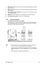
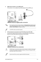
... MICPWR Line out_R NC Line out_L PORT1 L PORT1 R PORT2 R SENSE_SEND PORT2 L M4N68T-M V2 HD-audio-compliant Legacy AC'97 pin definition compliant definition M4N68T-M Series Analog front panel connector • We recommend that supports either High Definition Audio or AC`97 audio standard.... 1.10.2 Internal connectors 1. ASUS M4N68T-M Series 1-21 7. These two 4-pin Universal Serial Bus (USB) ports connect to USB 2.0 devices. 8. This 9-pin COM1 port is for a chassis-mounted front panel audio I/O module that you connect a high-definition front panel audio module to this connector, ...
... MICPWR Line out_R NC Line out_L PORT1 L PORT1 R PORT2 R SENSE_SEND PORT2 L M4N68T-M V2 HD-audio-compliant Legacy AC'97 pin definition compliant definition M4N68T-M Series Analog front panel connector • We recommend that supports either High Definition Audio or AC`97 audio standard.... 1.10.2 Internal connectors 1. ASUS M4N68T-M Series 1-21 7. These two 4-pin Universal Serial Bus (USB) ports connect to USB 2.0 devices. 8. This 9-pin COM1 port is for a chassis-mounted front panel audio I/O module that you connect a high-definition front panel audio module to this connector, ...
User Manual
Page 35
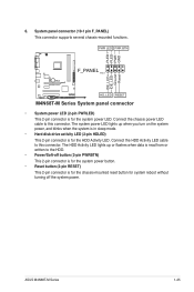
PLED+ PLEDPWR GND IDE_LED+ IDE_LED- System panel connector (10-1 pin F_PANEL) This connector supports several chassis-mounted functions. ASUS M4N68T-M Series 1-25 Ground Reset 6. Connect the chassis power LED cable to this connector. Connect the HDD Activity LED cable to ...(2-pin HDLED) This 2-pin connector is for system reboot without turning off the system power. PWR LED PWR BTN F_PANEL PIN 1 M4N68T-M V2 HD_LED RESET M4N68T-M Series System panel connector • System power LED (2-pin PWRLED) This 2-pin connector is for the chassis-mounted reset button for the HDD Activity...
PLED+ PLEDPWR GND IDE_LED+ IDE_LED- System panel connector (10-1 pin F_PANEL) This connector supports several chassis-mounted functions. ASUS M4N68T-M Series 1-25 Ground Reset 6. Connect the chassis power LED cable to this connector. Connect the HDD Activity LED cable to ...(2-pin HDLED) This 2-pin connector is for system reboot without turning off the system power. PWR LED PWR BTN F_PANEL PIN 1 M4N68T-M V2 HD_LED RESET M4N68T-M Series System panel connector • System power LED (2-pin PWRLED) This 2-pin connector is for the chassis-mounted reset button for the HDD Activity...
User Manual
Page 37
... CHA_FAN) Connect the fan cables to the fan connectors. CPU_FAN CPU FAN PWM CPU FAN IN CPU FAN PWR GND M4N68T-M V2 CHA_FAN Rotation +12V GND M4N68T-M Series fan connectors DO NOT forget to connect the fan cables to the fan connectors on the motherboard, ensuring that the...the connector. Go to Start > Control Panel > Sounds and Audio Devices > Sound Playback to configure the setting. Insufficient air flow inside the system may be different based on the fan connectors. ASUS M4N68T-M Series 1-27 Only the 4-pin CPU fan connector supports the ASUS Q-Fan feature. 8. DO NOT place...
... CHA_FAN) Connect the fan cables to the fan connectors. CPU_FAN CPU FAN PWM CPU FAN IN CPU FAN PWR GND M4N68T-M V2 CHA_FAN Rotation +12V GND M4N68T-M Series fan connectors DO NOT forget to connect the fan cables to the fan connectors on the motherboard, ensuring that the...the connector. Go to Start > Control Panel > Sounds and Audio Devices > Sound Playback to configure the setting. Insufficient air flow inside the system may be different based on the fan connectors. ASUS M4N68T-M Series 1-27 Only the 4-pin CPU fan connector supports the ASUS Q-Fan feature. 8. DO NOT place...

