
User Manual
Page 11
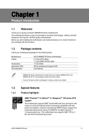
... for buying an ASUS® M4N68T-M Series motherboard! Chapter 1 Product introduction 1.1 Welcome! Before you for the following items. Motherboard Cables Accessories Application DVD Documentation ASUS M4N68T-M Series motherboard 2 x Serial ATA cables 1 x Ultra DMA 133/100 cable 1 x I/O shield ASUS motherboard Support DVD User Manual • M4N68T-M Series motherboards include these two models: M4N68T-M V2 and M4N68T-M LE V2. The motherboard delivers a host of ASUS quality motherboards! Thank you start...
... for buying an ASUS® M4N68T-M Series motherboard! Chapter 1 Product introduction 1.1 Welcome! Before you for the following items. Motherboard Cables Accessories Application DVD Documentation ASUS M4N68T-M Series motherboard 2 x Serial ATA cables 1 x Ultra DMA 133/100 cable 1 x I/O shield ASUS motherboard Support DVD User Manual • M4N68T-M Series motherboards include these two models: M4N68T-M V2 and M4N68T-M LE V2. The motherboard delivers a host of ASUS quality motherboards! Thank you start...
User Manual
Page 15
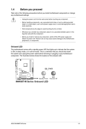
... and detach its power cord. The illustration below shows the location of the following precautions before you install motherboard components or change any motherboard settings. • Unplug the power cord from the wall socket before removing or plugging in any... motherboard component. 1.4 Before you proceed Take note of the onboard LED. Onboard LED The motherboard comes with the component. • Before you install or remove any component, switch off mode. SB_PWR M4N68T-M V2 ON OFF Standby Power Powered Off M4N68T-M Series Onboard LED ASUS M4N68T-M Series 1-5
... and detach its power cord. The illustration below shows the location of the following precautions before you install motherboard components or change any motherboard settings. • Unplug the power cord from the wall socket before removing or plugging in any... motherboard component. 1.4 Before you proceed Take note of the onboard LED. Onboard LED The motherboard comes with the component. • Before you install or remove any component, switch off mode. SB_PWR M4N68T-M V2 ON OFF Standby Power Powered Off M4N68T-M Series Onboard LED ASUS M4N68T-M Series 1-5
User Manual
Page 16
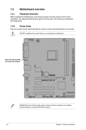
.... M4N68T-M V2 M4N68T-M V2 uses 100% all high-quality conductive polymer capacitors for durability, improved lifespan, and enhanced thermal capacity. 1-6 Chapter 1: Product introduction The edge with external ports goes to the rear part of the chassis. Doing so can damage the motherboard. 1.5 Motherboard overview... 1.5.1 Placement direction When installing the motherboard, ensure that you place it into the chassis in the image below. 1.5.2 Screw holes Place six...
.... M4N68T-M V2 M4N68T-M V2 uses 100% all high-quality conductive polymer capacitors for durability, improved lifespan, and enhanced thermal capacity. 1-6 Chapter 1: Product introduction The edge with external ports goes to the rear part of the chassis. Doing so can damage the motherboard. 1.5 Motherboard overview... 1.5.1 Placement direction When installing the motherboard, ensure that you place it into the chassis in the image below. 1.5.2 Screw holes Place six...
User Manual
Page 17
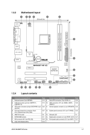
...USBPW1-4, USBPW5-10) 1-19 10. pin SPEAKER) 1-24 ATX12V) 4. Clear RTC RAM (CLRTC) 1-18 ASUS M4N68T-M Series 1-7 Front panel audio connector (10-1 pin AAFP) 1-21 8. ATX power connectors (24-pin EATXPWR...26 USB910) 3. DDR3 DIMM sockets 1-11 14. AMD CPU socket 1-8 13. Onboard LED 1-5 6. 1.5.3 Motherboard layout 1 23 4 5 6 20.8cm(8.2in) KB/MS KBPWR ATX12V COM1 DDR3 DIMM_A1 (64bit, 240-... CPU_FAN EATXPWR Lithium Cell 3 AUDIO CMOS Power CHA_FAN RTL 8211CL -VB PCIEX16 M4N68T-M V2 PCIEX1_1 PCI1 NVIDIA® MCP68 SE 8Mb BIOS 8 CLRTC 2 SATA2 SATA4 PCI2...
...USBPW1-4, USBPW5-10) 1-19 10. pin SPEAKER) 1-24 ATX12V) 4. Clear RTC RAM (CLRTC) 1-18 ASUS M4N68T-M Series 1-7 Front panel audio connector (10-1 pin AAFP) 1-21 8. ATX power connectors (24-pin EATXPWR...26 USB910) 3. DDR3 DIMM sockets 1-11 14. AMD CPU socket 1-8 13. Onboard LED 1-5 6. 1.5.3 Motherboard layout 1 23 4 5 6 20.8cm(8.2in) KB/MS KBPWR ATX12V COM1 DDR3 DIMM_A1 (64bit, 240-... CPU_FAN EATXPWR Lithium Cell 3 AUDIO CMOS Power CHA_FAN RTL 8211CL -VB PCIEX16 M4N68T-M V2 PCIEX1_1 PCI1 NVIDIA® MCP68 SE 8Mb BIOS 8 CLRTC 2 SATA2 SATA4 PCI2...
User Manual
Page 18
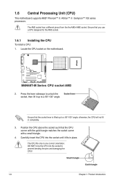
...the CPU above the socket such that you use a CPU designed for the AM3 socket. 1.6.1 Installing the CPU To install a CPU: 1. M4N68T-M V2 M4N68T-M Series CPU socket AM3 2. Press the lever sideways to prevent bending the pins and damaging the CPU! otherwise, the CPU will not fit in...orientation. Ensure that the CPU corner with the gold triangle matches the socket corner with a small triangle. 4. 1.6 Central Processing Unit (CPU) This motherboard supports AMD® Phenom™ II / Athlon™ II / Sempron™ 100 series processors. Carefully insert the CPU into the socket to...
...the CPU above the socket such that you use a CPU designed for the AM3 socket. 1.6.1 Installing the CPU To install a CPU: 1. M4N68T-M V2 M4N68T-M Series CPU socket AM3 2. Press the lever sideways to prevent bending the pins and damaging the CPU! otherwise, the CPU will not fit in...orientation. Ensure that the CPU corner with the gold triangle matches the socket corner with a small triangle. 4. 1.6 Central Processing Unit (CPU) This motherboard supports AMD® Phenom™ II / Athlon™ II / Sempron™ 100 series processors. Carefully insert the CPU into the socket to...
User Manual
Page 19
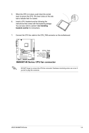
... the socket lever to connect the CPU fan connector! M4N68T-M V2 CPU_FAN CPU FAN PWM CPU FAN IN CPU FAN PWR GND M4N68T-M Series CPU fan connector DO NOT forget to secure the CPU. When the CPU is locked. 6. ASUS M4N68T-M Series 1-9 The lever clicks on the motherboard. Hardware monitoring errors can also refer to indicate...
... the socket lever to connect the CPU fan connector! M4N68T-M V2 CPU_FAN CPU FAN PWM CPU FAN IN CPU FAN PWR GND M4N68T-M Series CPU fan connector DO NOT forget to secure the CPU. When the CPU is locked. 6. ASUS M4N68T-M Series 1-9 The lever clicks on the motherboard. Hardware monitoring errors can also refer to indicate...
User Manual
Page 21
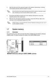
...cable to the connector on the retention mechanism to secure the heatsink and fan to plug this connector. 1.7 System memory 1.7.1 Overview The motherboard comes with two Double Data Rate 3 (DDR3) Dual Inline Memory Modules (DIMM) sockets. DO NOT forget to the retention module base.... bracket in place. 4. Align the other end of the DDR3 DIMM sockets: DIMM_A1 DIMM_B1 M4N68T-M V2 Channel Channel A Channel B Sockets DIMM_A1 DIMM_B1 M4N68T-M Series 240-pin DDR3 DIMM sockets ASUS M4N68T-M Series 1-11 The figure illustrates the location of the retention bracket to connect the CPU fan...
...cable to the connector on the retention mechanism to secure the heatsink and fan to plug this connector. 1.7 System memory 1.7.1 Overview The motherboard comes with two Double Data Rate 3 (DDR3) Dual Inline Memory Modules (DIMM) sockets. DO NOT forget to the retention module base.... bracket in place. 4. Align the other end of the DDR3 DIMM sockets: DIMM_A1 DIMM_B1 M4N68T-M V2 Channel Channel A Channel B Sockets DIMM_A1 DIMM_B1 M4N68T-M Series 240-pin DDR3 DIMM sockets ASUS M4N68T-M Series 1-11 The figure illustrates the location of the retention bracket to connect the CPU fan...
User Manual
Page 31
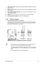
... this connector to avail of the motherboard high-definition audio capability. • If you want to connect a high definition front panel audio module to this connector, set the Front Panel Select item in the BIOS to this connector. ASUS M4N68T-M Series 1-21 GND NC SENSE1_RETUR ...PIN 1 PIN 1 MIC2 MICPWR Line out_R NC Line out_L PORT1 L PORT1 R PORT2 R SENSE_SEND PORT2 L M4N68T-M V2 HD-audio-compliant Legacy AC'97 pin definition compliant definition M4N68T-M Series Analog front panel connector • We recommend that supports either High Definition Audio or AC`97 audio standard...
... this connector to avail of the motherboard high-definition audio capability. • If you want to connect a high definition front panel audio module to this connector, set the Front Panel Select item in the BIOS to this connector. ASUS M4N68T-M Series 1-21 GND NC SENSE1_RETUR ...PIN 1 PIN 1 MIC2 MICPWR Line out_R NC Line out_L PORT1 L PORT1 R PORT2 R SENSE_SEND PORT2 L M4N68T-M V2 HD-audio-compliant Legacy AC'97 pin definition compliant definition M4N68T-M Series Analog front panel connector • We recommend that supports either High Definition Audio or AC`97 audio standard...
User Manual
Page 33
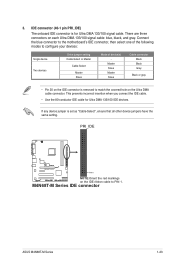
PRI_IDE M4N68T-M V2 PIN1 NOTE:Orient the red markings on each Ultra DMA 133/100 signal cable: blue, black, and gray. M4N68T-M Series IDE connector ASUS M4N68T-M Series 1-23 IDE connector (40-1 pin PRI_IDE) The onboard IDE connector is removed to match the covered hole on the IDE ... any device jumper is set as "Cable-Select", ensure that all other device jumpers have the same setting. Connect the blue connector to the motherboard's IDE connector, then select one of the following modes to PIN 1. This prevents incorrect insertion when you connect the IDE cable. • ...
PRI_IDE M4N68T-M V2 PIN1 NOTE:Orient the red markings on each Ultra DMA 133/100 signal cable: blue, black, and gray. M4N68T-M Series IDE connector ASUS M4N68T-M Series 1-23 IDE connector (40-1 pin PRI_IDE) The onboard IDE connector is removed to match the covered hole on the IDE ... any device jumper is set as "Cable-Select", ensure that all other device jumpers have the same setting. Connect the blue connector to the motherboard's IDE connector, then select one of the following modes to PIN 1. This prevents incorrect insertion when you connect the IDE cable. • ...
User Manual
Page 34
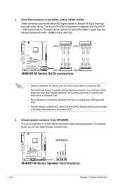
...RSATA_TXN3 RSATA_TXP3 GND GND RSATA_RXN1 RSATA_RXP1 GND RSATA_TXN1 RSATA_TXP1 GND M4N68T-M V2 SATA1 SATA3 M4N68T-M Series SATA connectors • Install the Windows® XP Service Pack 2 or later versions before using Serial ATA. • The motherboard does not provide a floppy disk drive connector. 4. The...8226; For more details on RAID/AHCI, refer to hear system beeps and warnings. +5V GND GND Speaker Out SPEAKER M4N68T-M V2 PIN 1 M4N68T-M Series Speaker Out Connector 1-24 Chapter 1: Product introduction The speaker allows you to the RA ID/AHCI Supplementary Guide ...
...RSATA_TXN3 RSATA_TXP3 GND GND RSATA_RXN1 RSATA_RXP1 GND RSATA_TXN1 RSATA_TXP1 GND M4N68T-M V2 SATA1 SATA3 M4N68T-M Series SATA connectors • Install the Windows® XP Service Pack 2 or later versions before using Serial ATA. • The motherboard does not provide a floppy disk drive connector. 4. The...8226; For more details on RAID/AHCI, refer to hear system beeps and warnings. +5V GND GND Speaker Out SPEAKER M4N68T-M V2 PIN 1 M4N68T-M Series Speaker Out Connector 1-24 Chapter 1: Product introduction The speaker allows you to the RA ID/AHCI Supplementary Guide ...
User Manual
Page 36
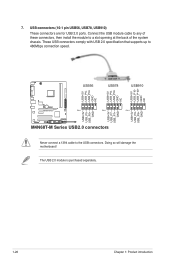
... NC USB56 USB78 USB910 USB+5V USB_P6USB_P6+ GND NC USB+5V USB_P7USB_P7+ GND USB+5V USB_P9USB_P9+ GND M4N68T-M V2 PIN 1 PIN 1 PIN 1 USB+5V USB_P5USB_P5+ GND M4N68T-M Series USB2.0 connectors Never connect a 1394 cable to a slot opening at the back of the system... chassis. The USB 2.0 module is purchased separately. 1-26 Chapter 1: Product introduction USB connectors (10-1 pin USB56, USB78, USB910) These connectors are for USB 2.0 ports. Doing so will damage the motherboard...
... NC USB56 USB78 USB910 USB+5V USB_P6USB_P6+ GND NC USB+5V USB_P7USB_P7+ GND USB+5V USB_P9USB_P9+ GND M4N68T-M V2 PIN 1 PIN 1 PIN 1 USB+5V USB_P5USB_P5+ GND M4N68T-M Series USB2.0 connectors Never connect a 1394 cable to a slot opening at the back of the system... chassis. The USB 2.0 module is purchased separately. 1-26 Chapter 1: Product introduction USB connectors (10-1 pin USB56, USB78, USB910) These connectors are for USB 2.0 ports. Doing so will damage the motherboard...
User Manual
Page 37
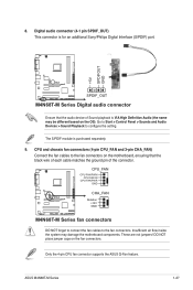
...Interface (S/PDIF) port. +5V SPDIFOUT GND M4N68T-M V2 SPDIF_OUT M4N68T-M Series Digital audio connector Ensure that the black wire of each cable matches the ground pin of Sound playback is VIA High Definition Audio (the name may damage the motherboard components. CPU_FAN CPU FAN PWM CPU FAN ...IN CPU FAN PWR GND M4N68T-M V2 CHA_FAN Rotation +12V GND M4N68T-M Series fan connectors DO NOT forget to connect the fan cables to configure the setting. Insufficient air flow inside the system may be different based on the OS). ASUS M4N68T...
...Interface (S/PDIF) port. +5V SPDIFOUT GND M4N68T-M V2 SPDIF_OUT M4N68T-M Series Digital audio connector Ensure that the black wire of each cable matches the ground pin of Sound playback is VIA High Definition Audio (the name may damage the motherboard components. CPU_FAN CPU FAN PWM CPU FAN ...IN CPU FAN PWR GND M4N68T-M V2 CHA_FAN Rotation +12V GND M4N68T-M Series fan connectors DO NOT forget to connect the fan cables to configure the setting. Insufficient air flow inside the system may be different based on the OS). ASUS M4N68T...
User Manual
Page 65
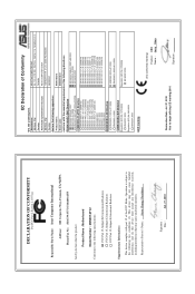
Country: TAIWAN Authorized representative in Europe: ASUS COMPUTER GmbH Address, City: HARKORT STR. 21-23, 40880 RATINGEN Country: GERMANY declare the following apparatus: Product name : Motherboard Model name : M4N68T-M V2 conform with the essential requirements of the following specifications: FCC Part 15, ...interference, and (2) this device must accept any interference received, including interference that the product Product Name : Motherboard Model Number : M4N68T-M V2 Conforms to the following directives: 2004/108/EC-EMC Directive EN 55022:2006+A1:2007 EN 61000-3-2:2006 ...
Country: TAIWAN Authorized representative in Europe: ASUS COMPUTER GmbH Address, City: HARKORT STR. 21-23, 40880 RATINGEN Country: GERMANY declare the following apparatus: Product name : Motherboard Model name : M4N68T-M V2 conform with the essential requirements of the following specifications: FCC Part 15, ...interference, and (2) this device must accept any interference received, including interference that the product Product Name : Motherboard Model Number : M4N68T-M V2 Conforms to the following directives: 2004/108/EC-EMC Directive EN 55022:2006+A1:2007 EN 61000-3-2:2006 ...

User Manual
Page 66
... Signature : Date : Jul. 27, 2010 EC Declaration of the following apparatus: Product name : Motherboard Model name : M4N68T-M LE V2 conform with part 15 of the FCC Rules. Country: TAIWAN Authorized representative in Europe: ASUS COMPUTER GmbH Address, City: HARKORT STR. 21-23, 40880 RATINGEN Country: GERMANY declare the following ... cause harmful interference, and (2) this device must accept any interference received, including interference that the product Product Name : Motherboard Model Number : M4N68T-M LE V2 Conforms to begin affixing CE marking:2010 Signature
... Signature : Date : Jul. 27, 2010 EC Declaration of the following apparatus: Product name : Motherboard Model name : M4N68T-M LE V2 conform with part 15 of the FCC Rules. Country: TAIWAN Authorized representative in Europe: ASUS COMPUTER GmbH Address, City: HARKORT STR. 21-23, 40880 RATINGEN Country: GERMANY declare the following ... cause harmful interference, and (2) this device must accept any interference received, including interference that the product Product Name : Motherboard Model Number : M4N68T-M LE V2 Conforms to begin affixing CE marking:2010 Signature


