
User Manual
Page 3
... guide vii M4N68T-M Series specifications summary ix Chapter 1: Product introduction 1.1 Welcome 1-1 1.2 Package contents 1-1 1.3 Special features 1-1 1.3.1 Product highlights 1-1 1.3.2 Innovative ASUS features 1-3 1.4 Before you proceed 1-5 1.5 Motherboard overview 1-6 1.5.1 Placement direction 1-6 1.5.2 Screw holes 1-6 1.5.3 Motherboard layout 1-7 1.5.4 Layout contents 1-7 1.6 Central Processing Unit (CPU 1-8 1.6.1 Installing the CPU 1-8 1.6.2 Installing the heatsink and fan 1-10 1.7 System memory 1-11 1.7.1 Overview 1-11 1.7.2 Memory configurations 1-12...
... guide vii M4N68T-M Series specifications summary ix Chapter 1: Product introduction 1.1 Welcome 1-1 1.2 Package contents 1-1 1.3 Special features 1-1 1.3.1 Product highlights 1-1 1.3.2 Innovative ASUS features 1-3 1.4 Before you proceed 1-5 1.5 Motherboard overview 1-6 1.5.1 Placement direction 1-6 1.5.2 Screw holes 1-6 1.5.3 Motherboard layout 1-7 1.5.4 Layout contents 1-7 1.6 Central Processing Unit (CPU 1-8 1.6.1 Installing the CPU 1-8 1.6.2 Installing the heatsink and fan 1-10 1.7 System memory 1-11 1.7.1 Overview 1-11 1.7.2 Memory configurations 1-12...
User Manual
Page 9
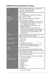
... 1 x VGA port 1 x COM port 4 x USB 2.0/1.1 ports 1 x LPT port 3 x Audio jacks (continued on the next page) ix M4N68T-M Series specifications summary CPU Chipset Front side bus Memory Graphics Expansion slots Storage / RAID LAN Audio USB Back panel I/O ports AMD® Socket AM3 for AMD® Phenom™ II... enables simultaneous 32-bit and 64-bit computing * Refer to www.asus.com for the AMD® CPU support list GeForce 7025 / nForce 630a 2000 / 1600 MT/s HyperTransport™ 1.0 interface Dual-channel memory architecture 2 x 240-pin DIMM slots support maximum 8GB unbuffered ECC and...
... 1 x VGA port 1 x COM port 4 x USB 2.0/1.1 ports 1 x LPT port 3 x Audio jacks (continued on the next page) ix M4N68T-M Series specifications summary CPU Chipset Front side bus Memory Graphics Expansion slots Storage / RAID LAN Audio USB Back panel I/O ports AMD® Socket AM3 for AMD® Phenom™ II... enables simultaneous 32-bit and 64-bit computing * Refer to www.asus.com for the AMD® CPU support list GeForce 7025 / nForce 630a 2000 / 1600 MT/s HyperTransport™ 1.0 interface Dual-channel memory architecture 2 x 240-pin DIMM slots support maximum 8GB unbuffered ECC and...
User Manual
Page 11
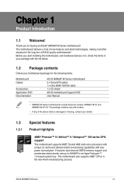
..., making it , check the items in your motherboard package for buying an ASUS® M4N68T-M Series motherboard! The package contents vary with models. • If any of ASUS quality motherboards! This motherboard also supports AMD® CPUs in the long line... Application DVD Documentation ASUS M4N68T-M Series motherboard 2 x Serial ATA cables 1 x Ultra DMA 133/100 cable 1 x I/O shield ASUS motherboard Support DVD User Manual • M4N68T-M Series motherboards include these two models: M4N68T-M V2 and M4N68T-M LE V2. It features dual-channel DDR3 memory support and accelerates data...
..., making it , check the items in your motherboard package for buying an ASUS® M4N68T-M Series motherboard! The package contents vary with models. • If any of ASUS quality motherboards! This motherboard also supports AMD® CPUs in the long line... Application DVD Documentation ASUS M4N68T-M Series motherboard 2 x Serial ATA cables 1 x Ultra DMA 133/100 cable 1 x I/O shield ASUS motherboard Support DVD User Manual • M4N68T-M Series motherboards include these two models: M4N68T-M V2 and M4N68T-M LE V2. It features dual-channel DDR3 memory support and accelerates data...
User Manual
Page 12
... quiet operating environment. It is a highly integrated Gb LAN controller. Dual-Channel DDR3 1800 (O.C.) support This motherboard supports DDR3 memory that features data transfer rates of 1800 (O.C.)/1600 (O.C.)/1333/1066 MHz to provide efficient power management for advanced operating systems. Serial... ATA 3Gb/s technology and RAID support This motherboard supports hard drives based on M4N68T-M only) This motherboard uses high-quality conductive polymer capacitors for Serial ATA hard drives. 8-channel high definition audio The ...
... quiet operating environment. It is a highly integrated Gb LAN controller. Dual-Channel DDR3 1800 (O.C.) support This motherboard supports DDR3 memory that features data transfer rates of 1800 (O.C.)/1600 (O.C.)/1333/1066 MHz to provide efficient power management for advanced operating systems. Serial... ATA 3Gb/s technology and RAID support This motherboard supports hard drives based on M4N68T-M only) This motherboard uses high-quality conductive polymer capacitors for Serial ATA hard drives. 8-channel high definition audio The ...
User Manual
Page 21
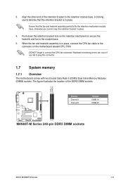
... bracket lock on the motherboard labeled CPU_FAN. Align the other end of the DDR3 DIMM sockets: DIMM_A1 DIMM_B1 M4N68T-M V2 Channel Channel A Channel B Sockets DIMM_A1 DIMM_B1 M4N68T-M Series 240-pin DDR3 DIMM sockets ASUS M4N68T-M Series 1-11 Ensure that the retention bracket is in place, connect the CPU fan cable to the connector... base. When the fan and heatsink assembly is in place. 4. The figure illustrates the location of the retention bracket to plug this connector. 1.7 System memory 1.7.1 Overview The motherboard comes with two Double Data Rate 3 (DDR3) Dual Inline...
... bracket lock on the motherboard labeled CPU_FAN. Align the other end of the DDR3 DIMM sockets: DIMM_A1 DIMM_B1 M4N68T-M V2 Channel Channel A Channel B Sockets DIMM_A1 DIMM_B1 M4N68T-M Series 240-pin DDR3 DIMM sockets ASUS M4N68T-M Series 1-11 Ensure that the retention bracket is in place, connect the CPU fan cable to the connector... base. When the fan and heatsink assembly is in place. 4. The figure illustrates the location of the retention bracket to plug this connector. 1.7 System memory 1.7.1 Overview The motherboard comes with two Double Data Rate 3 (DDR3) Dual Inline...
User Manual
Page 22
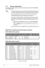
... Crucial Crucial Part No. Size SS/DS Brand Chip NO. M4N68T-M Series Motherboard Qualified Vendors Lists (QVL) DDR3-1800(O.C.)MHz capability Vendor Part No. For optimum compatibility, we recommend that you obtain memory modules from the higher-sized channel is then mapped for the ...512MB, 1GB, 2GB, and 4GB unbuffered ECC and non-ECC DDR3 DIMMs into the DIMM sockets. • You may install varying memory sizes in ��g�a��3�2�-�b�it�W��i�n�d�o�w��s® OS....
... Crucial Crucial Part No. Size SS/DS Brand Chip NO. M4N68T-M Series Motherboard Qualified Vendors Lists (QVL) DDR3-1800(O.C.)MHz capability Vendor Part No. For optimum compatibility, we recommend that you obtain memory modules from the higher-sized channel is then mapped for the ...512MB, 1GB, 2GB, and 4GB unbuffered ECC and non-ECC DDR3 DIMMs into the DIMM sockets. • You may install varying memory sizes in ��g�a��3�2�-�b�it�W��i�n�d�o�w��s® OS....
User Manual
Page 25
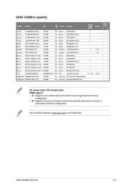
...: Single-sided / DS: Double-sided DIMM support: • A*: Supports one module inserted into either slot as single-channel memory configuration. • B*: Supports one pair of modules inserted into both the blue slots as one pair of dual-channel memory configuration. ASUS M4N68T-M Series 1-15 Visit the ASUS website at www.asus.com for the latest QVL.
...: Single-sided / DS: Double-sided DIMM support: • A*: Supports one module inserted into either slot as single-channel memory configuration. • B*: Supports one pair of modules inserted into both the blue slots as one pair of dual-channel memory configuration. ASUS M4N68T-M Series 1-15 Visit the ASUS website at www.asus.com for the latest QVL.
User Manual
Page 28
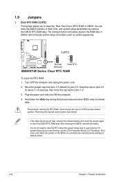
CLRTC 12 23 M4N68T-M V2 Normal (Default) Clear RTC M4N68T-M Series Clear RTC RAM To erase the RTC RAM: 1. Turn OFF the computer and unplug the power cord. 2. Keep the cap on CLRTC jumper default ... pins 2-3 for about 5~10 seconds, then move the jumper again to pins 1-2. 3. Hold down and reboot the system so the BIOS can clear the CMOS memory of date, time, and system setup parameters by erasing the CMOS RTC RAM data. After clearing the CMOS, reinstall the battery. • You do not...
CLRTC 12 23 M4N68T-M V2 Normal (Default) Clear RTC M4N68T-M Series Clear RTC RAM To erase the RTC RAM: 1. Turn OFF the computer and unplug the power cord. 2. Keep the cap on CLRTC jumper default ... pins 2-3 for about 5~10 seconds, then move the jumper again to pins 1-2. 3. Hold down and reboot the system so the BIOS can clear the CMOS memory of date, time, and system setup parameters by erasing the CMOS RTC RAM data. After clearing the CMOS, reinstall the battery. • You do not...
User Manual
Page 47
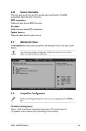
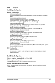
... [Auto] Selects the CPU overclocking options to malfunction. Configuration options: [Manual] [Auto] [Standard] [Overclock Profile] ASUS M4N68T-M Series 2-9 Processor Displays the auto-detected CPU specification. BIOS Information Displays the auto-detected BIOS information. 2.3.5 System Information...Configuration Chipset Onboard Devices Configuration PCIPnP USB Configuration Version 0301 Adjust System Frequency/Voltage etc. System Memory Displays the auto-detected system memory. 2.4 Advanced menu The Advanced menu items allow you an overview of the Advanced menu items....
... [Auto] Selects the CPU overclocking options to malfunction. Configuration options: [Manual] [Auto] [Standard] [Overclock Profile] ASUS M4N68T-M Series 2-9 Processor Displays the auto-detected CPU specification. BIOS Information Displays the auto-detected BIOS information. 2.3.5 System Information...Configuration Chipset Onboard Devices Configuration PCIPnP USB Configuration Version 0301 Adjust System Frequency/Voltage etc. System Memory Displays the auto-detected system memory. 2.4 Advanced menu The Advanced menu items allow you an overview of the Advanced menu items....

User Manual
Page 49
...system becomes unstable after changing the setting, set Memory Clock Mode to adjust the value. The values range from 1.5000V to adjust the value. Memory Clock Mode [Auto] Sets the memory clock mode. Use the / keys to [...memory over voltage. Use the / keys to 2.4450V with a 0.01000V increment. Configuration options: [Auto] LoadLine Calibration [Auto] Sets the LoadLine. Configuration options: [Auto] [Max. = 2.4450V] [Min. = 1.5000V] Chipset Over Voltage [Auto] Sets the chipset over voltage. Configuration options: [Auto] [Max. = 1.60000V] [Min. = 1.20000V] ASUS M4N68T...
...system becomes unstable after changing the setting, set Memory Clock Mode to adjust the value. The values range from 1.5000V to adjust the value. Memory Clock Mode [Auto] Sets the memory clock mode. Use the / keys to [...memory over voltage. Use the / keys to 2.4450V with a 0.01000V increment. Configuration options: [Auto] LoadLine Calibration [Auto] Sets the LoadLine. Configuration options: [Auto] [Max. = 2.4450V] [Min. = 1.5000V] Chipset Over Voltage [Auto] Sets the chipset over voltage. Configuration options: [Auto] [Max. = 1.60000V] [Min. = 1.20000V] ASUS M4N68T...
User Manual
Page 51
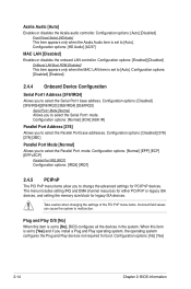
...-Stating during C3 and Alt VID. Configuration options: [Auto] [32MB] [64MB] [128MB] [256MB] ASUS M4N68T-M Series 2-13 Configuration options: [Disabled] [Enabled] DCT Unganged Mode [Always] Allows you to enable or disable memory remapping around memory hole. Configuration options: [Disabled] [Enabled] Memory Hole Remapping [Enabled] Allows you to select the unganged DRAM mode (64-bit width...
...-Stating during C3 and Alt VID. Configuration options: [Auto] [32MB] [64MB] [128MB] [256MB] ASUS M4N68T-M Series 2-13 Configuration options: [Disabled] [Enabled] DCT Unganged Mode [Always] Allows you to enable or disable memory remapping around memory hole. Configuration options: [Disabled] [Enabled] Memory Hole Remapping [Enabled] Allows you to select the unganged DRAM mode (64-bit width...
User Manual
Page 52
...] [Yes] 2-14 Chapter 2: BIOS information The menu includes setting IRQ and DMA channel resources for either PCI/PnP or legacy ISA devices, and setting the memory size block for boot. Take caution when changing the settings of the PCI PnP menu items. Incorrect field values can cause the system to [No...
...] [Yes] 2-14 Chapter 2: BIOS information The menu includes setting IRQ and DMA channel resources for either PCI/PnP or legacy ISA devices, and setting the memory size block for boot. Take caution when changing the settings of the PCI PnP menu items. Incorrect field values can cause the system to [No...

User Manual
Page 61
Profile Utility V1.44 Current CMOS BOARD: M4N68T-M-V2 VER: 0303 (H:00 B:00) DATE: 07/1209/2010 Restore CMOS BOARD: Unknown VER: Unknown DATE: Unknown PATH: C:\ C: Note [Enter] Select or Load [Tab] Switch [... only coming from the same memory/CPU configuration and BIOS version. • Only the CMO file can be loaded. 2.7.3 AI NET 2 Check Realtek Phy LAN cable [Disabled] Enables or disables checking of the Realtek LAN cable during the Power-On Self‑Test (POST). Configuration options: [Disabled] [Enabled] ASUS M4N68T-M Series 2-23 ASUSTek O.C.
Profile Utility V1.44 Current CMOS BOARD: M4N68T-M-V2 VER: 0303 (H:00 B:00) DATE: 07/1209/2010 Restore CMOS BOARD: Unknown VER: Unknown DATE: Unknown PATH: C:\ C: Note [Enter] Select or Load [Tab] Switch [... only coming from the same memory/CPU configuration and BIOS version. • Only the CMO file can be loaded. 2.7.3 AI NET 2 Check Realtek Phy LAN cable [Disabled] Enables or disables checking of the Realtek LAN cable during the Power-On Self‑Test (POST). Configuration options: [Disabled] [Enabled] ASUS M4N68T-M Series 2-23 ASUSTek O.C.


