
User Manual
Page 4
...an operating system 1-28 1.11.2 Support DVD information 1-28 Chapter 2: BIOS information 2.1 Managing and updating your BIOS 2-1 2.1.1 ASUS Update utility 2-1 2.1.2 ASUS EZ Flash 2 utility 2-2 2.1.3 ASUS CrashFree BIOS utility 2-3 2.2 BIOS setup program 2-4 2.2.1 BIOS menu screen 2-5 2.2.3 Navigation keys 2-5 2.2.2 Menu bar 2-5 2.2.4... 2-12 2.4.3 Chipset 2-13 2.4.4 Onboard Device Configuration 2-14 2.4.5 PCIPnP 2-14 2.4.6 USB Configuration 2-15 2.5 Power menu 2-16 2.5.1 Suspend Mode [Auto 2-16 2.5.2 ACPI 2.0 Support [Enabled 2-16 2.5.3 ACPI APIC Support [Enabled 2-16 iv
...an operating system 1-28 1.11.2 Support DVD information 1-28 Chapter 2: BIOS information 2.1 Managing and updating your BIOS 2-1 2.1.1 ASUS Update utility 2-1 2.1.2 ASUS EZ Flash 2 utility 2-2 2.1.3 ASUS CrashFree BIOS utility 2-3 2.2 BIOS setup program 2-4 2.2.1 BIOS menu screen 2-5 2.2.3 Navigation keys 2-5 2.2.2 Menu bar 2-5 2.2.4... 2-12 2.4.3 Chipset 2-13 2.4.4 Onboard Device Configuration 2-14 2.4.5 PCIPnP 2-14 2.4.6 USB Configuration 2-15 2.5 Power menu 2-16 2.5.1 Suspend Mode [Auto 2-16 2.5.2 ACPI 2.0 Support [Enabled 2-16 2.5.3 ACPI APIC Support [Enabled 2-16 iv
User Manual
Page 7
... BIOS information This chapter tells how to change system settings through the BIOS Setup menus. If you are using, contact your local power company. • If the power supply is broken, do not try to fix it , carefully read all the manuals that came with the product, contact a ...contact your retailer. Do not place the product in your retailer. Safety information Electrical safety • To prevent electric shock hazard, disconnect the power cable from the electric outlet before relocating the system. • When adding or removing devices to or from the system, ensure that all ...
... BIOS information This chapter tells how to change system settings through the BIOS Setup menus. If you are using, contact your local power company. • If the power supply is broken, do not try to fix it , carefully read all the manuals that came with the product, contact a ...contact your retailer. Do not place the product in your retailer. Safety information Electrical safety • To prevent electric shock hazard, disconnect the power cable from the electric outlet before relocating the system. • When adding or removing devices to or from the system, ensure that all ...
User Manual
Page 10
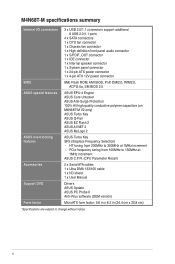
... 1 x 4-pin ATX 12V power connector BIOS ASUS special features ASUS overclocking features 8Mb Flash ROM, AMI BIOS, PnP, DMI2.0, WfM2.0, ACPI2.0a, SM BIOS 2.5 ASUS EPU-4 Engine ASUS Core Unlocker ASUS Anti-Surge Protection 100% All high quality conductive polymer capacitors (on M4N68T-M V2 only) ASUS Turbo Key ASUS Q-Fan ASUS EZ Flash 2 ASUS AI NET 2 ASUS MyLogo 2 ASUS Turbo Key SFS (Stepless...
... 1 x 4-pin ATX 12V power connector BIOS ASUS special features ASUS overclocking features 8Mb Flash ROM, AMI BIOS, PnP, DMI2.0, WfM2.0, ACPI2.0a, SM BIOS 2.5 ASUS EPU-4 Engine ASUS Core Unlocker ASUS Anti-Surge Protection 100% All high quality conductive polymer capacitors (on M4N68T-M V2 only) ASUS Turbo Key ASUS Q-Fan ASUS EZ Flash 2 ASUS AI NET 2 ASUS MyLogo 2 ASUS Turbo Key SFS (Stepless...
User Manual
Page 11
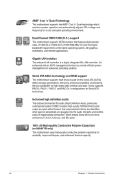
... and delivers better overclocking capabilities with the list below. 1.2 Package contents Check your package with less power consumption. This motherboard also supports AMD® CPUs in your motherboard package for buying an ASUS® M4N68T-M Series motherboard! ASUS M4N68T-M Series 1-1 The package contents vary with models. • If any of new features and latest technologies...
... and delivers better overclocking capabilities with the list below. 1.2 Package contents Check your package with less power consumption. This motherboard also supports AMD® CPUs in your motherboard package for buying an ASUS® M4N68T-M Series motherboard! ASUS M4N68T-M Series 1-1 The package contents vary with models. • If any of new features and latest technologies...
User Manual
Page 12
...-detect feature that features data transfer rates of 1800 (O.C.)/1600 (O.C.)/1333/1066 MHz to provide efficient power management for advanced operating systems. Serial ATA 3Gb/s technology and RAID support This motherboard supports hard drives based on M4N68T-M only) This motherboard uses high-quality conductive polymer capacitors for durability, improved lifespan, and enhanced...
...-detect feature that features data transfer rates of 1800 (O.C.)/1600 (O.C.)/1333/1066 MHz to provide efficient power management for advanced operating systems. Serial ATA 3Gb/s technology and RAID support This motherboard supports hard drives based on M4N68T-M only) This motherboard uses high-quality conductive polymer capacitors for durability, improved lifespan, and enhanced...
User Manual
Page 13
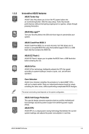
... cores, without interrupting ongoing work or games, simply through pressing the button. ASUS M4N68T-M Series 1-3 1.3.2 Innovative ASUS features ASUS Turbo Key ASUS Turbo Key allows you to turn the PC power button into 256-color boot logos to personalize your favorite photos into an overclocking... button. ASUS CrashFree BIOS 3 ASUS CrashFree BIOS 3 is a unique power saving technology that detects the current system loadings and adjusts the power consumption in real time. After the easy setup, Turbo Key boosts...
... cores, without interrupting ongoing work or games, simply through pressing the button. ASUS M4N68T-M Series 1-3 1.3.2 Innovative ASUS features ASUS Turbo Key ASUS Turbo Key allows you to turn the PC power button into 256-color boot logos to personalize your favorite photos into an overclocking... button. ASUS CrashFree BIOS 3 ASUS CrashFree BIOS 3 is a unique power saving technology that detects the current system loadings and adjusts the power consumption in real time. After the easy setup, Turbo Key boosts...
User Manual
Page 15
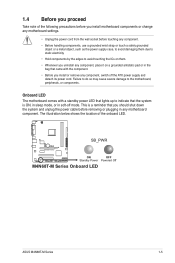
... • Before handling components, use a grounded wrist strap or touch a safely grounded object or a metal object, such as the power supply case, to avoid damaging them due to static electricity. • Hold components by the edges to the motherboard, peripherals, or ... uninstall any component, place it on them. • Whenever you install or remove any motherboard component. SB_PWR M4N68T-M V2 ON OFF Standby Power Powered Off M4N68T-M Series Onboard LED ASUS M4N68T-M Series 1-5 Failure to do so may cause severe damage to avoid touching the ICs on a grounded antistatic pad...
... • Before handling components, use a grounded wrist strap or touch a safely grounded object or a metal object, such as the power supply case, to avoid damaging them due to static electricity. • Hold components by the edges to the motherboard, peripherals, or ... uninstall any component, place it on them. • Whenever you install or remove any motherboard component. SB_PWR M4N68T-M V2 ON OFF Standby Power Powered Off M4N68T-M Series Onboard LED ASUS M4N68T-M Series 1-5 Failure to do so may cause severe damage to avoid touching the ICs on a grounded antistatic pad...
User Manual
Page 17
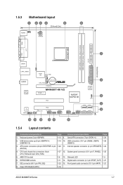
... AM3 VGA LPT 7 USBPW1-4 USB34 24.4cm(9.6in) LAN1_USB12 Super I/O CPU_FAN EATXPWR Lithium Cell 3 AUDIO CMOS Power CHA_FAN RTL 8211CL -VB PCIEX16 M4N68T-M V2 PCIEX1_1 PCI1 NVIDIA® MCP68 SE 8Mb BIOS 8 CLRTC 2 SATA2 SATA4 PCI2 VIA VT1708S SB_PWR F_PANEL USB56... Connectors/Jumpers/Slots Page 1. USB connectors (10-1 pin USB56, USB78, 1-26 USB910) 3. Internal speaker connector (4- Clear RTC RAM (CLRTC) 1-18 ASUS M4N68T-M Series 1-7 Front panel audio connector (10-1 pin AAFP) 1-21 8. Serial ATA connectors (7-pin SATA1-4) 1-24 2. AMD CPU socket 1-8 13....
... AM3 VGA LPT 7 USBPW1-4 USB34 24.4cm(9.6in) LAN1_USB12 Super I/O CPU_FAN EATXPWR Lithium Cell 3 AUDIO CMOS Power CHA_FAN RTL 8211CL -VB PCIEX16 M4N68T-M V2 PCIEX1_1 PCI1 NVIDIA® MCP68 SE 8Mb BIOS 8 CLRTC 2 SATA2 SATA4 PCI2 VIA VT1708S SB_PWR F_PANEL USB56... Connectors/Jumpers/Slots Page 1. USB connectors (10-1 pin USB56, USB78, 1-26 USB910) 3. Internal speaker connector (4- Clear RTC RAM (CLRTC) 1-18 ASUS M4N68T-M Series 1-7 Front panel audio connector (10-1 pin AAFP) 1-21 8. Serial ATA connectors (7-pin SATA1-4) 1-24 2. AMD CPU socket 1-8 13....
User Manual
Page 26
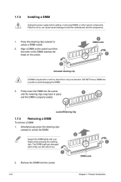
... only one direction. Locked Retaining Clip 1.7.4 Removing a DIMM To remove a DIMM: 1. Firmly insert the DIMM into a socket to unlock a DIMM socket. 2. 1.7.3 Installing a DIMM Unplug the power supply before adding or removing DIMMs or other system components. Press the retaining clips outward to avoid damaging the DIMM. 3. Align a DIMM on the socket...
... only one direction. Locked Retaining Clip 1.7.4 Removing a DIMM To remove a DIMM: 1. Firmly insert the DIMM into a socket to unlock a DIMM socket. 2. 1.7.3 Installing a DIMM Unplug the power supply before adding or removing DIMMs or other system components. Press the retaining clips outward to avoid damaging the DIMM. 3. Align a DIMM on the socket...
User Manual
Page 27
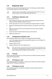
... a chassis). 3. Turn on BIOS setup. 2. Unplug the power cord before adding or removing expansion cards. Keep the screw for information on the system and change the necessary BIOS settings, if any. Remove the bracket opposite the slot that they support. Failure to use . 4. ASUS M4N68T-M Series 1-17 Align the card connector with the...
... a chassis). 3. Turn on BIOS setup. 2. Unplug the power cord before adding or removing expansion cards. Keep the screw for information on the system and change the necessary BIOS settings, if any. Remove the bracket opposite the slot that they support. Failure to use . 4. ASUS M4N68T-M Series 1-17 Align the card connector with the...
User Manual
Page 28
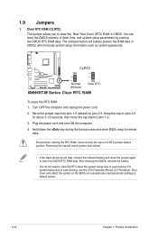
...power cord. 2. Keep the cap on CLRTC jumper default position. Removing the cap will cause system boot failure! • If the steps above do not need to clear the RTC when the system hangs due to clear the CMOS RTC RAM data. CLRTC 12 23 M4N68T...system setup parameters by erasing the CMOS RTC RAM data. The onboard button cell battery powers the RAM data in CMOS. Move the jumper cap from pins 1-2 (default) to...Shut down the key during the boot process and enter BIOS setup to pins 2-3. Plug the power cord and turn ON the computer. 4. For system failure due to clear the Real Time...
...power cord. 2. Keep the cap on CLRTC jumper default position. Removing the cap will cause system boot failure! • If the steps above do not need to clear the RTC when the system hangs due to clear the CMOS RTC RAM data. CLRTC 12 23 M4N68T...system setup parameters by erasing the CMOS RTC RAM data. The onboard button cell battery powers the RAM data in CMOS. Move the jumper cap from pins 1-2 (default) to...Shut down the key during the boot process and enter BIOS setup to pins 2-3. Plug the power cord and turn ON the computer. 4. For system failure due to clear the Real Time...
User Manual
Page 29
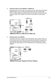
... (3-pin USBPW1-4, USBPW5-10) Set these jumpers to +5VSB to CPU, DRAM in slow refresh, power supply in low power mode) using the connected USB devices. KBPWR 12 23 +5V +5VSB (Default) M4N68T-M V2 M4N68T-M Series Keyboard Power Setting ASUS M4N68T-M Series 1-19 USBPW1-4 12 23 +5V +5VSB (Default) M4N68T-M V2 USBPW5-10 12 23 +5V +5VSB (Default...
... (3-pin USBPW1-4, USBPW5-10) Set these jumpers to +5VSB to CPU, DRAM in slow refresh, power supply in low power mode) using the connected USB devices. KBPWR 12 23 +5V +5VSB (Default) M4N68T-M V2 M4N68T-M Series Keyboard Power Setting ASUS M4N68T-M Series 1-19 USBPW1-4 12 23 +5V +5VSB (Default) M4N68T-M V2 USBPW5-10 12 23 +5V +5VSB (Default...
User Manual
Page 32
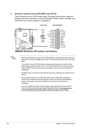
... GND GND +3 Volts +12 Volts +12 Volts +5V Standby Power OK PIN 1 GND +5 Volts GND +5 Volts GND +3 Volts +3 Volts PIN 1 M4N68T-M Series ATX power connectors GND +5 Volts +5 Volts +5 Volts -5 Volts GND GND GND PSON# GND -12 Volts +3 Volts • We...power rating of 300W power rating. The plugs from the power supply are for an ATX power supply. ATX power connectors (24-pin EATXPWR, 4-pin ATX12V) These connectors are designed to the Recommended Power Supply Wattage Calculator at least 15 A on +12 V and that the 20-pin power plug can provide at http://support.asus...
... GND GND +3 Volts +12 Volts +12 Volts +5V Standby Power OK PIN 1 GND +5 Volts GND +5 Volts GND +3 Volts +3 Volts PIN 1 M4N68T-M Series ATX power connectors GND +5 Volts +5 Volts +5 Volts -5 Volts GND GND GND PSON# GND -12 Volts +3 Volts • We...power rating of 300W power rating. The plugs from the power supply are for an ATX power supply. ATX power connectors (24-pin EATXPWR, 4-pin ATX12V) These connectors are designed to the Recommended Power Supply Wattage Calculator at least 15 A on +12 V and that the 20-pin power plug can provide at http://support.asus...
User Manual
Page 35
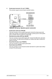
...pin connector is for the chassis-mounted reset button for the system power LED. PLED+ PLEDPWR GND IDE_LED+ IDE_LED- PWR LED PWR BTN F_PANEL PIN 1 M4N68T-M V2 HD_LED RESET M4N68T-M Series System panel connector • System power LED (2-pin PWRLED) This 2-pin connector is for the HDD ...the chassis power LED cable to the HDD. • Power/Soft-off the system power. System panel connector (10-1 pin F_PANEL) This connector supports several chassis-mounted functions. The system power LED lights up or flashes when data is read from or written to this connector. ASUS M4N68T-M Series ...
...pin connector is for the chassis-mounted reset button for the system power LED. PLED+ PLEDPWR GND IDE_LED+ IDE_LED- PWR LED PWR BTN F_PANEL PIN 1 M4N68T-M V2 HD_LED RESET M4N68T-M Series System panel connector • System power LED (2-pin PWRLED) This 2-pin connector is for the HDD ...the chassis power LED cable to the HDD. • Power/Soft-off the system power. System panel connector (10-1 pin F_PANEL) This connector supports several chassis-mounted functions. The system power LED lights up or flashes when data is read from or written to this connector. ASUS M4N68T-M Series ...

User Manual
Page 42
...continues with its parameters. Using the power button, reset button, or the ++ keys to force reset from the operating system. • The default BIOS settings for reference only. 2.2 BIOS setup program Use the BIOS Setup program to your screen. • Visit the ASUS website at startup: • ...Press during the Power-On Self-Test (POST). Entering BIOS Setup at startup To enter BIOS Setup at www.asus.com to ensure system compatibility and stability. If the system becomes unstable after...
...continues with its parameters. Using the power button, reset button, or the ++ keys to force reset from the operating system. • The default BIOS settings for reference only. 2.2 BIOS setup program Use the BIOS Setup program to your screen. • Visit the ASUS website at startup: • ...Press during the Power-On Self-Test (POST). Entering BIOS Setup at startup To enter BIOS Setup at www.asus.com to ensure system compatibility and stability. If the system becomes unstable after...
User Manual
Page 43
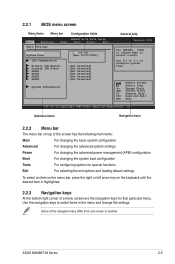
...and Exit ESC Exit v02.61 (C)Copyright 1985-2009, American Megatrends, Inc. ASUS M4N68T-M Series 2-5 2.2.1 BIOS menu screen Menu items Menu bar Configuration fields Main Advanced M4N68T-M-V2 BIOS Setup Power Boot Tools Exit Main Settings System Time [22:03:55] System Date ... following main items: Main For changing the basic system configuration Advanced For changing the advanced system settings Power For changing the advanced power management (APM) configuration Boot For changing the system boot configuration Tools For configuring options for that particular...
...and Exit ESC Exit v02.61 (C)Copyright 1985-2009, American Megatrends, Inc. ASUS M4N68T-M Series 2-5 2.2.1 BIOS menu screen Menu items Menu bar Configuration fields Main Advanced M4N68T-M-V2 BIOS Setup Power Boot Tools Exit Main Settings System Time [22:03:55] System Date ... following main items: Main For changing the basic system configuration Advanced For changing the advanced system settings Power For changing the advanced power management (APM) configuration Boot For changing the system boot configuration Tools For configuring options for that particular...
User Manual
Page 44
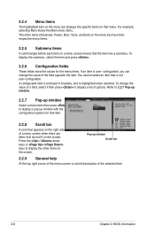
... for the menu items. If an item is not user-configurable. Refer to 2.2.7 Pop-up window. 2.2.7 Pop-up window Main Advanced M4N68T-M-V2 UTILITY Power Boot Tools Exit Select a menu item then press Suspend Mode ACPI 2.0 Support ACPI APIC support to display the other items (Advanced..., Power, Boot, Tools, and Exit) on the menu bar have their respective menu items. 2.2.5 Submenu items A solid triangle before each item on the screen...
... for the menu items. If an item is not user-configurable. Refer to 2.2.7 Pop-up window. 2.2.7 Pop-up window Main Advanced M4N68T-M-V2 UTILITY Power Boot Tools Exit Select a menu item then press Suspend Mode ACPI 2.0 Support ACPI APIC support to display the other items (Advanced..., Power, Boot, Tools, and Exit) on the menu bar have their respective menu items. 2.2.5 Submenu items A solid triangle before each item on the screen...
User Manual
Page 45
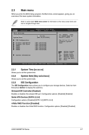
... [SATA1,2,3,4] Configuration options: [Disabled] [SATA 1,2] [SATA1,2,3,4] nVidia RAID Function [Disabled] Enables or disables the nVidia RAID function. Configuration options: [Disabled] [Enabled] ASUS M4N68T-M Series 2-7 Main Advanced Main Settings M4N68T-M-V2 BIOS Setup Power Boot Tools Exit System Time [22:03:55] System Date [Mon 01/07/2002] IDE Configuration Primary IDE Master Primary IDE...
... [SATA1,2,3,4] Configuration options: [Disabled] [SATA 1,2] [SATA1,2,3,4] nVidia RAID Function [Disabled] Enables or disables the nVidia RAID function. Configuration options: [Disabled] [Enabled] ASUS M4N68T-M Series 2-7 Main Advanced Main Settings M4N68T-M-V2 BIOS Setup Power Boot Tools Exit System Time [22:03:55] System Date [Mon 01/07/2002] IDE Configuration Primary IDE Master Primary IDE...
User Manual
Page 47
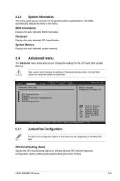
... CPU and other system devices. Select Screen Select Item +- Configuration options: [Manual] [Auto] [Standard] [Overclock Profile] ASUS M4N68T-M Series 2-9 2.3.5 System Information This menu gives you to achieve desired CPU internal frequency. Main Advanced Advanced Settings Power M4N68T-M-V2 BIOS Setup Boot Tools Exit JumperFree Configuration CPU Configuration Chipset Onboard Devices Configuration PCIPnP USB Configuration...
... CPU and other system devices. Select Screen Select Item +- Configuration options: [Manual] [Auto] [Standard] [Overclock Profile] ASUS M4N68T-M Series 2-9 2.3.5 System Information This menu gives you to achieve desired CPU internal frequency. Main Advanced Advanced Settings Power M4N68T-M-V2 BIOS Setup Boot Tools Exit JumperFree Configuration CPU Configuration Chipset Onboard Devices Configuration PCIPnP USB Configuration...

User Manual
Page 50
... operation. Configuration options: [Disabled] [Enabled] Secure Virtual Machine Mode [Disabled] Enables or disables Secure Virtual Machine Mode (SVM). Configuration options: [Enabled] [Disabled] ASUS Core Unlocker [Disabled] Enables the ASUS Core Unlocker to disable this menu show the CPU-related information that the BIOS automatically detects. Select [Disabled] to get the full computing...
... operation. Configuration options: [Disabled] [Enabled] Secure Virtual Machine Mode [Disabled] Enables or disables Secure Virtual Machine Mode (SVM). Configuration options: [Enabled] [Disabled] ASUS Core Unlocker [Disabled] Enables the ASUS Core Unlocker to disable this menu show the CPU-related information that the BIOS automatically detects. Select [Disabled] to get the full computing...


