

Uk Manual
Page 1
... and instructions in the space above for future reference. If you have questions, or if there are missing parts, please contact us: Call: 08457 089 009 From Ireland: 00 (44) 53 9236102 Website: www.iconsupport.eu E-mail: [email protected] Write: ICON Health & Fitness, Ltd. Serial Number Decal (under bench) QUESTIONS? WEEVBE7023.0 Serial No. Write the serial number in this manual before using this manual...
... and instructions in the space above for future reference. If you have questions, or if there are missing parts, please contact us: Call: 08457 089 009 From Ireland: 00 (44) 53 9236102 Website: www.iconsupport.eu E-mail: [email protected] Write: ICON Health & Fitness, Ltd. Serial Number Decal (under bench) QUESTIONS? WEEVBE7023.0 Serial No. Write the serial number in this manual before using this manual...

Uk Manual
Page 2
Apply the decal in the location shown. Note: The decal(s) may not be shown at actual size. WEIDER is missing or illegible, see the front cover of this manual and request a free replacement decal. If a decal is a registered trademark of the warning decal(s). TABLE OF CONTENTS WARNING DECAL PLACEMENT 2 IMPORTANT PRECAUTIONS 3 BEFORE YOU BEGIN 4 PART IDENTIFICATION CHART 5 ASSEMBLY 6 ADJUSTMENT 9 PART LIST 10 EXPLODED DRAWING 11 ORDERING REPLACEMENT PARTS Back Cover WARNING DECAL PLACEMENT This drawing shows the location(s) of ICON IP, Inc. 2
Apply the decal in the location shown. Note: The decal(s) may not be shown at actual size. WEIDER is missing or illegible, see the front cover of this manual and request a free replacement decal. If a decal is a registered trademark of the warning decal(s). TABLE OF CONTENTS WARNING DECAL PLACEMENT 2 IMPORTANT PRECAUTIONS 3 BEFORE YOU BEGIN 4 PART IDENTIFICATION CHART 5 ASSEMBLY 6 ADJUSTMENT 9 PART LIST 10 EXPLODED DRAWING 11 ORDERING REPLACEMENT PARTS Back Cover WARNING DECAL PLACEMENT This drawing shows the location(s) of ICON IP, Inc. 2
Uk Manual
Page 3
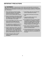
... by or through the use it to support a maximum user weight of 300 lbs. (135 kg), a maximum dumbbell weight of 110 lbs. (50 kg), and a maximum total weight of this manual and all parts regularly. When using the weight bench, make sure that the lock pins are fully inserted and are adequately informed of all precautions. 4. Replace any exercise program, consult your weight bench. Keep hands and feet...
... by or through the use it to support a maximum user weight of 300 lbs. (135 kg), a maximum dumbbell weight of 110 lbs. (50 kg), and a maximum total weight of this manual and all parts regularly. When using the weight bench, make sure that the lock pins are fully inserted and are adequately informed of all precautions. 4. Replace any exercise program, consult your weight bench. Keep hands and feet...
Uk Manual
Page 4
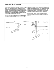
... after reading this manual, please see the front cover of exercises designed to achieve the specific results you , note the product model number and serial number before using the weight bench. Bench Pivot Leg Foam Pad Lock Pin Foam Pad Adjustment Leg 4 For your cardiovascular system, the weight bench will help us . Before reading further, please look at the drawing below and familiarize yourself with the parts that are...
... after reading this manual, please see the front cover of exercises designed to achieve the specific results you , note the product model number and serial number before using the weight bench. Bench Pivot Leg Foam Pad Lock Pin Foam Pad Adjustment Leg 4 For your cardiovascular system, the weight bench will help us . Before reading further, please look at the drawing below and familiarize yourself with the parts that are...
Uk Manual
Page 5
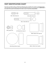
M6 x 16mm Screw (5) M6 x 48mm Screw (4) M10 x 70mm Bolt (14) M10 Locknut (13) 3/4" Round Inner Cap (7) 38mm Square Inner Cap (16) 50mm Round Outer Cap (9) 38mm x 50mm Inner Cap (8) 5 PART IDENTIFICATION CHART This chart is provided to help you cannot find a part in the hardware kit, check to the key number of the part from the PART LIST near the end of this manual. IMPORTANT: If you identify the small parts used in parentheses below each part refers to see if it has been preassembled. The number in assembly.
M6 x 16mm Screw (5) M6 x 48mm Screw (4) M10 x 70mm Bolt (14) M10 Locknut (13) 3/4" Round Inner Cap (7) 38mm Square Inner Cap (16) 50mm Round Outer Cap (9) 38mm x 50mm Inner Cap (8) 5 PART IDENTIFICATION CHART This chart is provided to help you cannot find a part in the hardware kit, check to the key number of the part from the PART LIST near the end of this manual. IMPORTANT: If you identify the small parts used in parentheses below each part refers to see if it has been preassembled. The number in assembly.
Uk Manual
Page 6
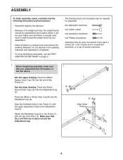
... Adjustment Leg (3). Align these holes 1 11 9 3 9 6 ASSEMBLY To make sure 1 that you have a socket set, a set of open-end or closed-end wrenches, or a set of the Frame (1). Make sure that there is completed. • For help identifying small parts, use the PART IDENTIFICATION CHART on page 5. • The following information and instructions: • Assembly requires two persons. • Because of its weight and size, the weight bench...
... Adjustment Leg (3). Align these holes 1 11 9 3 9 6 ASSEMBLY To make sure 1 that you have a socket set, a set of open-end or closed-end wrenches, or a set of the Frame (1). Make sure that there is completed. • For help identifying small parts, use the PART IDENTIFICATION CHART on page 5. • The following information and instructions: • Assembly requires two persons. • Because of its weight and size, the weight bench...
Uk Manual
Page 7
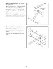
... Tubes (10). 3 6 7 10 6 7 3 10 7 6 7 6 7 Press two 50mm Round Outer Caps (9) onto the Pivot Leg (2). Secure the Pivot Leg (2) by inserting the L-pin (15) through the indicated hole in the Pivot Leg and the corresponding hole in the Pivot Leg (2) with the M10 x 70mm Bolt (14) and the M10 Locknut (13). Attach the Pivot Leg (2) to the Frame (1) with the...
... Tubes (10). 3 6 7 10 6 7 3 10 7 6 7 6 7 Press two 50mm Round Outer Caps (9) onto the Pivot Leg (2). Secure the Pivot Leg (2) by inserting the L-pin (15) through the indicated hole in the Pivot Leg and the corresponding hole in the Pivot Leg (2) with the M10 x 70mm Bolt (14) and the M10 Locknut (13). Attach the Pivot Leg (2) to the Frame (1) with the...
Uk Manual
Page 8
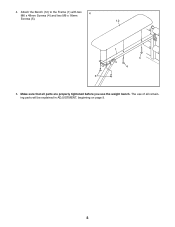
Attach the Bench (12) to the Frame (1) with two 4 M6 x 48mm Screws (4) and two M6 x 16mm Screws (5). 12 1 4 4 5 5. The use of all parts are properly tightened before you use the weight bench. Make sure that all remaining parts will be explained in ADJUSTMENT, beginning on page 9. 8 4.
Attach the Bench (12) to the Frame (1) with two 4 M6 x 48mm Screws (4) and two M6 x 16mm Screws (5). 12 1 4 4 5 5. The use of all parts are properly tightened before you use the weight bench. Make sure that all remaining parts will be explained in ADJUSTMENT, beginning on page 9. 8 4.

Uk Manual
Page 9
... weight bench can be used . Make sure that both Lock Pins (11). Reinsert both Lock Pins are properly tightened each time the weight bench is designed to clean the weight bench. ADJUSTMENT The weight bench is used with the corresponding hole in place around the Adjustment Leg. 12 1 3 11 9 Refer to the accompanying exercise guide to the exercise information accompanying your own weight set (not included). Refer also to see the correct form...
... weight bench can be used . Make sure that both Lock Pins (11). Reinsert both Lock Pins are properly tightened each time the weight bench is designed to clean the weight bench. ADJUSTMENT The weight bench is used with the corresponding hole in place around the Adjustment Leg. 12 1 3 11 9 Refer to the accompanying exercise guide to the exercise information accompanying your own weight set (not included). Refer also to see the correct form...
Uk Manual
Page 10
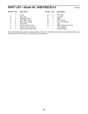
... Leg 3 1 Adjustment Leg 4 2 M6 x 48mm Screw 5 2 M6 x 16mm Screw 6 4 Foam Pad 7 4 3/4" Round Inner Cap 8 1 38mm x 50mm Inner Cap 9 4 50mm Round Outer Cap 10 2 Pad Tube 11 2 Lock Pin 12 1 Bench 13 1 M10 Locknut 14 1 M10 x 70mm Bolt 15 1 L-pin 16 1 38mm Square Inner Cap * - Userʼs Manual * - Exercise Guide Note: Specifications are not illustrated. 10 Qty. Qty. PART LIST-Model No. For information about ordering replacement parts, see the back cover...
... Leg 3 1 Adjustment Leg 4 2 M6 x 48mm Screw 5 2 M6 x 16mm Screw 6 4 Foam Pad 7 4 3/4" Round Inner Cap 8 1 38mm x 50mm Inner Cap 9 4 50mm Round Outer Cap 10 2 Pad Tube 11 2 Lock Pin 12 1 Bench 13 1 M10 Locknut 14 1 M10 x 70mm Bolt 15 1 L-pin 16 1 38mm Square Inner Cap * - Userʼs Manual * - Exercise Guide Note: Specifications are not illustrated. 10 Qty. Qty. PART LIST-Model No. For information about ordering replacement parts, see the back cover...
Uk Manual
Page 11
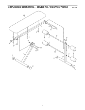
EXPLODED DRAWING-Model No. WEEVBE7023.0 R0310A 12 16 5 9 4 13 2 1 11 4 10 6 7 7 14 15 10 9 8 7 7 6 3 9 9 11
EXPLODED DRAWING-Model No. WEEVBE7023.0 R0310A 12 16 5 9 4 13 2 1 11 4 10 6 7 7 14 15 10 9 8 7 7 6 3 9 9 11

Uk Manual
Page 12
To help us assist you, be prepared to provide the following information when contacting us: • the model number and serial number of the product (see the front cover of this manual) • the name of the product (see the front cover of this manual) • the key number and description of the replacement part(s) (see the front cover of this manual. ORDERING REPLACEMENT PARTS To order replacement parts, please see the PART LIST and the EXPLODED DRAWING near the end of this manual) Part No. 197220 R0310A Printed in China © 2010 ICON IP, Inc.
To help us assist you, be prepared to provide the following information when contacting us: • the model number and serial number of the product (see the front cover of this manual) • the name of the product (see the front cover of this manual) • the key number and description of the replacement part(s) (see the front cover of this manual. ORDERING REPLACEMENT PARTS To order replacement parts, please see the PART LIST and the EXPLODED DRAWING near the end of this manual) Part No. 197220 R0310A Printed in China © 2010 ICON IP, Inc.


