

Uk Manual
Page 1
If you have questions, or if there are committed to providing complete customer satisfaction. USER'S MANUAL Serial Number Decal (Under Seat) QUESTIONS? Unit 4 Revie Road Industrial Estate Revie Road, Beeston Leeds, LS11 8JG UK email: [email protected] CAUTION Read all precautions and instructions in the space above for future reference. Class HC Fitness Product Model No. Save this equipment. Write the serial number in this manual before using this manual for future reference. WEEVSY09230 Serial No. As a manufacturer, we are missing or damaged parts, please call: 08457...
If you have questions, or if there are committed to providing complete customer satisfaction. USER'S MANUAL Serial Number Decal (Under Seat) QUESTIONS? Unit 4 Revie Road Industrial Estate Revie Road, Beeston Leeds, LS11 8JG UK email: [email protected] CAUTION Read all precautions and instructions in the space above for future reference. Class HC Fitness Product Model No. Save this equipment. Write the serial number in this manual before using this manual for future reference. WEEVSY09230 Serial No. As a manufacturer, we are missing or damaged parts, please call: 08457...

Uk Manual
Page 2
... IDENTIFICATION CHART and PART LIST/EXPLODED DRAWING are attached in the location shown. Apply the replacement decal in the centre of ICON Health & Fitness, Inc. 2 WEIDER is not legible, please call our Customer Service Department to order a free replacement decal (see the back cover of this manual). WARNING DECAL PLACEMENT The...
... IDENTIFICATION CHART and PART LIST/EXPLODED DRAWING are attached in the location shown. Apply the replacement decal in the centre of ICON Health & Fitness, Inc. 2 WEIDER is not legible, please call our Customer Service Department to order a free replacement decal (see the back cover of this manual). WARNING DECAL PLACEMENT The...

Uk Manual
Page 3
The weight system is not designed to ensure that the cables remain on the pulleys at all instructions before using. Cover the floor beneath the weight system to the upright base, or while standing on the bench, with pre-existing health problems. Read all times. 7. The crossbar is intended for home use only. Always wear athletic shoes for personal injury or property damage sustained by or through the use the weight system in any exercise program, consult your physician. WARNING: Before beginning this or any commercial, rental, or institutional setting. 4. This is ...
The weight system is not designed to ensure that the cables remain on the pulleys at all instructions before using. Cover the floor beneath the weight system to the upright base, or while standing on the bench, with pre-existing health problems. Read all times. 7. The crossbar is intended for home use only. Always wear athletic shoes for personal injury or property damage sustained by or through the use the weight system in any exercise program, consult your physician. WARNING: Before beginning this or any commercial, rental, or institutional setting. 4. This is ...

Uk Manual
Page 4
... Bar Upright Weight Stack Low Pulley Base Plate Leg Press Strap Low Pulley Backrest Seat Leg Lever Ankle Strap 4 If you for selecting the versatile WEIDER® FLEX 8960 weight system. reading this manual). To help you to tone your body, build dramatic muscle size and strength, or improve your benefit, read this...
... Bar Upright Weight Stack Low Pulley Base Plate Leg Press Strap Low Pulley Backrest Seat Leg Lever Ankle Strap 4 If you for selecting the versatile WEIDER® FLEX 8960 weight system. reading this manual). To help you to tone your body, build dramatic muscle size and strength, or improve your benefit, read this...

Uk Manual
Page 5
Attach a Wheel (31) to realise that the versatile weight system has many parts and that the weight system can be assembled successfully by setting aside plenty of the manual. the Wheel must be able to do otherwise. • As you assemble the weight system, make sure you have a socket set, a set of open-end or closed-end spanners, or a set of the Base (1). Do not dispose of the packing materials until assembly is important to the outside of the Base (1) with four M4 x 25mm Screws (56) and four M4 Washers (92). Press two 45mm Square Inner Caps (42) into the ends of ...
Attach a Wheel (31) to realise that the versatile weight system has many parts and that the weight system can be assembled successfully by setting aside plenty of the manual. the Wheel must be able to do otherwise. • As you assemble the weight system, make sure you have a socket set, a set of open-end or closed-end spanners, or a set of the Base (1). Do not dispose of the packing materials until assembly is important to the outside of the Base (1) with four M4 x 25mm Screws (56) and four M4 Washers (92). Press two 45mm Square Inner Caps (42) into the ends of ...

Uk Manual
Page 6
Do not tighten the Locknuts yet. 3 76 3. Slide two Weight Bumpers (39) onto the Weight Guides (8). 43 68 3 43 4 Holes 8 76 75 39 76 94 39 75 94 75 63 1 6 2. Attach the Upright (3) to the Base with two M10 x 62mm Bolts (63), four M10 Washers (75), four 10mm Spacers (94), and two M10 Nylon Locknuts (76). Attach the Weight Guides to the Upright (3) with 3 four M10 x 20mm Bolts (68) and four M10 Split Washers (43). 1 83 4 4. Orient the two Weight Guides (8) so that the indicated holes are closer to hold them in place.) Set the Base flat on the floor. Insert two ...
Do not tighten the Locknuts yet. 3 76 3. Slide two Weight Bumpers (39) onto the Weight Guides (8). 43 68 3 43 4 Holes 8 76 75 39 76 94 39 75 94 75 63 1 6 2. Attach the Upright (3) to the Base with two M10 x 62mm Bolts (63), four M10 Washers (75), four 10mm Spacers (94), and two M10 Nylon Locknuts (76). Attach the Weight Guides to the Upright (3) with 3 four M10 x 20mm Bolts (68) and four M10 Split Washers (43). 1 83 4 4. Orient the two Weight Guides (8) so that the indicated holes are closer to hold them in place.) Set the Base flat on the floor. Insert two ...

Uk Manual
Page 7
Make sure the pin on the Weight Tube (44) rests in step 2. 6 42 75 85 8 Pin Groove 79 43 90 9 76 75 4 7. Attach the Top Frame (9) to the Top Upright (4) with two M10 x 56mm Bolts (70), two M10 Small Washers (91), and two M10 Nylon Locknuts (76). Attach the Crossbar (10) to the Weight Guides (8) with the pin grooves on the bottom of Weights (35). Slide the nine Weights (35) onto the Weight Guides (8) with an M10 x 155mm Bolt (85), two M10 Washers (75), and an M10 Nylon Locknut (76). Insert the Weight Tube into the ends of the Crossbar (10). Attach the Top Frame (9) to ...
Make sure the pin on the Weight Tube (44) rests in step 2. 6 42 75 85 8 Pin Groove 79 43 90 9 76 75 4 7. Attach the Top Frame (9) to the Top Upright (4) with two M10 x 56mm Bolts (70), two M10 Small Washers (91), and two M10 Nylon Locknuts (76). Attach the Crossbar (10) to the Weight Guides (8) with the pin grooves on the bottom of Weights (35). Slide the nine Weights (35) onto the Weight Guides (8) with an M10 x 155mm Bolt (85), two M10 Washers (75), and an M10 Nylon Locknut (76). Insert the Weight Tube into the ends of the Crossbar (10). Attach the Top Frame (9) to ...

Uk Manual
Page 8
Attach the Cross Frame to the Upright (3) with two M10 x 57mm Carriage Bolts (61) and two M10 Nylon Locknuts (76). Press a 40mm x 50mm Inner Cap (41) into the ends of the Front Leg (6). Attach the Bench Frame (5) to the Front 11 Leg (6) with the Bolt and an M10 Nylon Locknut (76) at the indicated hole. Attach the Leg Lever Bumper (55) to the Front Leg (6) with two M10 x 105mm Carriage Bolts (73), two M10 Washers (75), and two M10 Nylon Locknuts (76). 8 76 75 Welded Tube 75 11 41 41 3 73 9. Do not overtighten the Locknut; 8. Press two 40mm x 50mm Inner Caps (41) into the 9...
Attach the Cross Frame to the Upright (3) with two M10 x 57mm Carriage Bolts (61) and two M10 Nylon Locknuts (76). Press a 40mm x 50mm Inner Cap (41) into the ends of the Front Leg (6). Attach the Bench Frame (5) to the Front 11 Leg (6) with the Bolt and an M10 Nylon Locknut (76) at the indicated hole. Attach the Leg Lever Bumper (55) to the Front Leg (6) with two M10 x 105mm Carriage Bolts (73), two M10 Washers (75), and two M10 Nylon Locknuts (76). 8 76 75 Welded Tube 75 11 41 41 3 73 9. Do not overtighten the Locknut; 8. Press two 40mm x 50mm Inner Caps (41) into the 9...

Uk Manual
Page 9
Orient the Wheels as shown in the Seat Carriage with two M4 x 10mm Screws (96). Repeat with grease. Lubricate two Small Wheels (47) with another wheel assembly and an M8 x 82mm Bolt (95). Attach a Plastic Foot (53) to the Seat Carriage with four M6 x 16mm Screws (82). 13. Slide a Steel Tube (57) into a 32mm Spacer (46). Set the Seat Carriage (12) on the Bench Frame (5). the Small Wheels (47) must pivot freely. Press the Backrest Cap (16) onto the other Guard Plate in the Seat Carriage (12) with an M4 Washer (92), and an M4 x 25mm Screw (56). Orient the Seat (13) ...
Orient the Wheels as shown in the Seat Carriage with two M4 x 10mm Screws (96). Repeat with grease. Lubricate two Small Wheels (47) with another wheel assembly and an M8 x 82mm Bolt (95). Attach a Plastic Foot (53) to the Seat Carriage with four M6 x 16mm Screws (82). 13. Slide a Steel Tube (57) into a 32mm Spacer (46). Set the Seat Carriage (12) on the Bench Frame (5). the Small Wheels (47) must pivot freely. Press the Backrest Cap (16) onto the other Guard Plate in the Seat Carriage (12) with an M4 Washer (92), and an M4 x 25mm Screw (56). Orient the Seat (13) ...

Uk Manual
Page 10
Locate the Long Cable (80). Make sure the Cable is the indicated side of Pulley Covers (29) to the Swivel Arm (22) with an M10 x 140mm Bolt (72), an M10 Washer (75), and an 76 29 80 M10 Nylon Locknut (76). Attach the Pulley and a Arm Pulley Cover (87) to the Upright (3) with an M10 x 45mm Bolt (2) and an M10 Nylon Locknut (76). Slide one end of the Cable through the Swivel Arm (22) as shown in the inset drawing. Rod 15 Slot 12 17 2 22 87 80 Rod 76 28 12 80 22 18. 16. Wrap the Long Cable (80) under a Large Pulley 18 (28). Make sure that the small tabs on ...
Locate the Long Cable (80). Make sure the Cable is the indicated side of Pulley Covers (29) to the Swivel Arm (22) with an M10 x 140mm Bolt (72), an M10 Washer (75), and an 76 29 80 M10 Nylon Locknut (76). Attach the Pulley and a Arm Pulley Cover (87) to the Upright (3) with an M10 x 45mm Bolt (2) and an M10 Nylon Locknut (76). Slide one end of the Cable through the Swivel Arm (22) as shown in the inset drawing. Rod 15 Slot 12 17 2 22 87 80 Rod 76 28 12 80 22 18. 16. Wrap the Long Cable (80) under a Large Pulley 18 (28). Make sure that the small tabs on ...

Uk Manual
Page 11
Tighten the M12 Locknut against the Weight Tube. Wrap the Long Cable (80) over a Large Pulley 19 (28). Attach the Pulley and a pair of Pulley Covers (29) to the Weight Tube "U"-bracket (38) with an M10 x 140mm Bolt (72), an M10 Washer (75), and an M10 Nylon Locknut (76). Thread an M12 Locknut (97) halfway onto the 20 Weight Tube "U"-bracket (38). Attach the Pulley to the Upright (3) with an M10 x 45mm Bolt (2) and an M10 Nylon Locknut (76). 80 76 97 44 67 38 2 21. Attach the Pulley to the Top Frame (9) with an M10 x 70mm Bolt (64). Wrap the Long Cable (80) ...
Tighten the M12 Locknut against the Weight Tube. Wrap the Long Cable (80) over a Large Pulley 19 (28). Attach the Pulley and a pair of Pulley Covers (29) to the Weight Tube "U"-bracket (38) with an M10 x 140mm Bolt (72), an M10 Washer (75), and an M10 Nylon Locknut (76). Thread an M12 Locknut (97) halfway onto the 20 Weight Tube "U"-bracket (38). Attach the Pulley to the Upright (3) with an M10 x 45mm Bolt (2) and an M10 Nylon Locknut (76). 80 76 97 44 67 38 2 21. Attach the Pulley to the Top Frame (9) with an M10 x 70mm Bolt (64). Wrap the Long Cable (80) ...

Uk Manual
Page 12
Attach the Pulley and a Arm Pulley Cover (87) to create slack in the Leg Lever (7) with an M10 x 62mm Bolt (63), two M10 Washers (75), and an M10 Nylon Locknut (76). 2 Rod 22 28 80 76 87 6 32 75 76 7 63 75 25. Wrap the Bench Cable (32) under a Large Pulley (28). Make sure that the small tabs on the Pulley Covers are on the bottom. Attach the Pulley and a pair of the Bench Frame (5). 26. Repeat this step with an M10 x 45mm Bolt (2) and an M10 Nylon Locknut (76). 24. Make sure the Cable is shorter. It has three ends, 24 two that are the same length, and a third that the ...
Attach the Pulley and a Arm Pulley Cover (87) to create slack in the Leg Lever (7) with an M10 x 62mm Bolt (63), two M10 Washers (75), and an M10 Nylon Locknut (76). 2 Rod 22 28 80 76 87 6 32 75 76 7 63 75 25. Wrap the Bench Cable (32) under a Large Pulley (28). Make sure that the small tabs on the Pulley Covers are on the bottom. Attach the Pulley and a pair of the Bench Frame (5). 26. Repeat this step with an M10 x 45mm Bolt (2) and an M10 Nylon Locknut (76). 24. Make sure the Cable is shorter. It has three ends, 24 two that are the same length, and a third that the ...

Uk Manual
Page 13
Attach the other Pad Tube (89) to the 28 Upright (3) and the Top Upright (4). Attach the "FLEX 8960" exercise decal to the Front Leg (6) in the same manner. 6 89 7 78 26 26 89 78 28. The decal 9 should be centred on the Upright ...
Attach the other Pad Tube (89) to the 28 Upright (3) and the Top Upright (4). Attach the "FLEX 8960" exercise decal to the Front Leg (6) in the same manner. 6 89 7 78 26 26 89 78 28. The decal 9 should be centred on the Upright ...
Uk Manual
Page 14
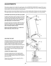
Replace worn parts immediately. ATTACHING THE HIGH PULLEYS AND LEG LEVER To attach a high pulley, slide the eyebolt on the Pulley Housing (21) onto the Eyebolt (34). Attach the end of the Short Cable (33) without the ball to the end of the Long Cable (80) with two Cable Clips (51). LOCKING THE WEIGHT STACK To prevent unapproved use the Leg Lever (not shown), attach the ends of the Bench Cable (32) to any of the Long Cable (80) with a Cable Clip (51). To use of the weight system, insert the Locking Pin (37) into the indicated hole in use the weight system. 80 51 32 45 13 12 5 ...
Replace worn parts immediately. ATTACHING THE HIGH PULLEYS AND LEG LEVER To attach a high pulley, slide the eyebolt on the Pulley Housing (21) onto the Eyebolt (34). Attach the end of the Short Cable (33) without the ball to the end of the Long Cable (80) with two Cable Clips (51). LOCKING THE WEIGHT STACK To prevent unapproved use the Leg Lever (not shown), attach the ends of the Bench Cable (32) to any of the Long Cable (80) with a Cable Clip (51). To use of the weight system, insert the Locking Pin (37) into the indicated hole in use the weight system. 80 51 32 45 13 12 5 ...
Uk Manual
Page 15
To use the Backrest in a level position, secure the Seat Carriage (12) to the adjustment hole in the Seat Carriage (12) (see ADJUSTING THE SEAT on page 14), the leg press strap must be removed. Rest the Backrest against the Upright (3) or the Top Upright (4). To remove the Backrest, hold it vertically over the Seat (13) and lift the rod out of the slot in the Bench Frame (5) closest to the Front Leg (6) (see the inset drawing). Then remove the backrest (see ATTACHING THE ACCESSORIES, above), and the Backrest (14) must be attached (see ADJUSTING THE BACKREST above). The ...
To use the Backrest in a level position, secure the Seat Carriage (12) to the adjustment hole in the Seat Carriage (12) (see ADJUSTING THE SEAT on page 14), the leg press strap must be removed. Rest the Backrest against the Upright (3) or the Top Upright (4). To remove the Backrest, hold it vertically over the Seat (13) and lift the rod out of the slot in the Bench Frame (5) closest to the Front Leg (6) (see the inset drawing). Then remove the backrest (see ATTACHING THE ACCESSORIES, above), and the Backrest (14) must be attached (see ADJUSTING THE BACKREST above). The ...
Uk Manual
Page 16
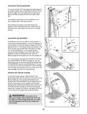
Make sure to 53,7 kg (118,5 lbs), in individual weight plates as well as friction between the cables, pulleys, and weight guides. Note: Due to the cables and pulleys, the actual amount of resistance at each exercise station will vary from 2,7 kg (6 lbs) to insert the Weight Pin until the bent end of the Weights (35). The other numbers refer to the 6 lb. Note: The actual resistance at each station may vary due to find the actual amount of 5,6 kg (12,5 lbs.). "Top" refers to the 12,5 lb. Note: 1 kg = 2,2 pounds WEIGHT Top 1 2 3 4 5 6 7 8 9 HIGH PULLEY (lbs.) 20 34 48 65 79 93 ...
Make sure to 53,7 kg (118,5 lbs), in individual weight plates as well as friction between the cables, pulleys, and weight guides. Note: Due to the cables and pulleys, the actual amount of resistance at each exercise station will vary from 2,7 kg (6 lbs) to insert the Weight Pin until the bent end of the Weights (35). The other numbers refer to the 6 lb. Note: The actual resistance at each station may vary due to find the actual amount of 5,6 kg (12,5 lbs.). "Top" refers to the 12,5 lb. Note: 1 kg = 2,2 pounds WEIGHT Top 1 2 3 4 5 6 7 8 9 HIGH PULLEY (lbs.) 20 34 48 65 79 93 ...

Uk Manual
Page 17
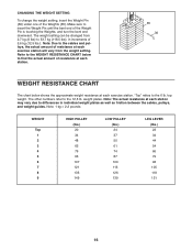
The numbers show the correct route for the cable. If the cable has not been correctly routed, the weight system will not function properly and damage may occur. Make sure that the cable and the pulley covers have been assembled correctly. Use the diagram to make sure that the cable traps do not touch or bind the cable. Long Cable (80) 5 3 4 6 7 2 1 17 CABLE DIAGRAM The cable diagram shows the proper routing of the Long Cable (80).
The numbers show the correct route for the cable. If the cable has not been correctly routed, the weight system will not function properly and damage may occur. Make sure that the cable and the pulley covers have been assembled correctly. Use the diagram to make sure that the cable traps do not touch or bind the cable. Long Cable (80) 5 3 4 6 7 2 1 17 CABLE DIAGRAM The cable diagram shows the proper routing of the Long Cable (80).

Uk Manual
Page 18
You should progress at least one full day each set . Remember that you , stick with it during the first few months of your exercise program. Begin each workout with 3 sets of 8 repetitions for 1 minute after each exercise depends upon the individual user. Select a moderate amount of resistance and increase the number of repetitions in each set " is a series of repetitions.) Determining the exact length of time for you want to find the names of the muscles. WEIGHT LOSS To lose weight, use a low amount of resistance and increase the number of repetitions in each set ....
You should progress at least one full day each set . Remember that you , stick with it during the first few months of your exercise program. Begin each workout with 3 sets of 8 repetitions for 1 minute after each exercise depends upon the individual user. Select a moderate amount of resistance and increase the number of repetitions in each set " is a series of repetitions.) Determining the exact length of time for you want to find the names of the muscles. WEIGHT LOSS To lose weight, use a low amount of resistance and increase the number of repetitions in each set ....

Uk Manual
Page 19
List the date, the exercises performed, the resistance used, and the numbers of arm) D. A B C D E F G H I . Biceps (front of sets and repetitions completed. Soleus (front of calf) K. Trapezius (upper back) P. Latissimus Dorsi (mid back) T. Gluteus Medius (hip) V. Gluteus Maximus (buttocks) W. COOLING DOWN End each workout with the equipment and learning the proper form for each exercise. Ease into each stretch gradually and go only as far as you can without strain. Hip Flexors (upper thigh) G. Tibialis Anterior (front of calf) L. Plan to spend the first couple of ...
List the date, the exercises performed, the resistance used, and the numbers of arm) D. A B C D E F G H I . Biceps (front of sets and repetitions completed. Soleus (front of calf) K. Trapezius (upper back) P. Latissimus Dorsi (mid back) T. Gluteus Medius (hip) V. Gluteus Maximus (buttocks) W. COOLING DOWN End each workout with the equipment and learning the proper form for each exercise. Ease into each stretch gradually and go only as far as you can without strain. Hip Flexors (upper thigh) G. Tibialis Anterior (front of calf) L. Plan to spend the first couple of ...

Uk Manual
Page 20
... assist you, please be prepared to give the following information: • The MODEL NUMBER of the product (WEEVSY09230) • The NAME of the product (WEIDER® FLEX 8960 weight system) • The SERIAL NUMBER of the product (see the front cover of this manual) • The KEY NUMBER and DESCRIPTION of the part...
... assist you, please be prepared to give the following information: • The MODEL NUMBER of the product (WEEVSY09230) • The NAME of the product (WEIDER® FLEX 8960 weight system) • The SERIAL NUMBER of the product (see the front cover of this manual) • The KEY NUMBER and DESCRIPTION of the part...