
English Manual
Page 1
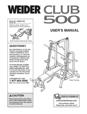
WEBE27322 Serial No. As a manufacturer, we are missing or damaged parts, we will provide immediate assistance, free of charge. Save this equipment. TO AVOID DELAYS, PLEASE CALL DIRECT TO OUR TOLLFREE CUSTOMER HOT LINE. MST CAUTION Read all precautions and instructions in the space above for future reference. If you have questions, or if there are committed to providing complete customer satisfaction. The trained technicians on our customer hot line will guarantee complete satisfaction through direct assistance from our factory. CUSTOMER HOT LINE: 1-877-992-5999 Mon.-Fri., 6 ...
WEBE27322 Serial No. As a manufacturer, we are missing or damaged parts, we will provide immediate assistance, free of charge. Save this equipment. TO AVOID DELAYS, PLEASE CALL DIRECT TO OUR TOLLFREE CUSTOMER HOT LINE. MST CAUTION Read all precautions and instructions in the space above for future reference. If you have questions, or if there are committed to providing complete customer satisfaction. The trained technicians on our customer hot line will guarantee complete satisfaction through direct assistance from our factory. CUSTOMER HOT LINE: 1-877-992-5999 Mon.-Fri., 6 ...
English Manual
Page 2
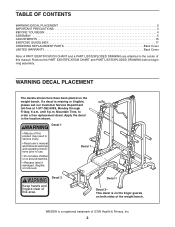
... a decal is a registered trademark of ICON Health & Fitness, Inc. 2 Decal 1 Decal 2- Decal 1 Decal 2 Keep hands and fingers clear of the weight bench. WEIDER is missing or illegible, please call our Customer Service Department toll-free at 1-877-992-5999, Monday through Friday, 6 a.m. WARNING DECAL PLACEMENT The decals shown ...
... a decal is a registered trademark of ICON Health & Fitness, Inc. 2 Decal 1 Decal 2- Decal 1 Decal 2 Keep hands and fingers clear of the weight bench. WEIDER is missing or illegible, please call our Customer Service Department toll-free at 1-877-992-5999, Monday through Friday, 6 a.m. WARNING DECAL PLACEMENT The decals shown ...
English Manual
Page 3
...does not require it. 16. Always exercise with the weight clips when they are exercising, stop immediately and begin cooling down. The weight bench is designed to catch the barbell if you are mounted on each time you feel pain or dizziness at the same height. 11. Always...the weight carriage. 6. IMPORTANT PRECAUTIONS WARNING: To reduce the risk of serious injury, read the following important precautions before using the weight bench. The weight bench is intended for persons over the age of 35 or persons with an Olympic barbell. 12. It is designed to be ready to ...
...does not require it. 16. Always exercise with the weight clips when they are exercising, stop immediately and begin cooling down. The weight bench is designed to catch the barbell if you are mounted on each time you feel pain or dizziness at the same height. 11. Always...the weight carriage. 6. IMPORTANT PRECAUTIONS WARNING: To reduce the risk of serious injury, read the following important precautions before using the weight bench. The weight bench is intended for persons over the age of 35 or persons with an Olympic barbell. 12. It is designed to be ready to ...
English Manual
Page 4
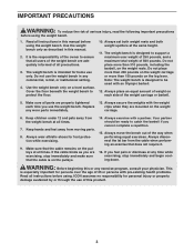
... Before reading further, please review the drawing below and familiarize yourself with the parts that are determined relative to help you for selecting the versatile WEIDER® CLUB 500 weight bench. Department toll-free at 1-877-992-5999, Monday through Friday, 6 a.m. The model number is designed to a person sitting on the...
... Before reading further, please review the drawing below and familiarize yourself with the parts that are determined relative to help you for selecting the versatile WEIDER® CLUB 500 weight bench. Department toll-free at 1-877-992-5999, Monday through Friday, 6 a.m. The model number is designed to a person sitting on the...
English Manual
Page 5
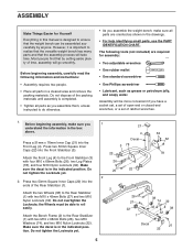
...packing materials until assembly is completed. • Tighten all parts are required for Yourself Everything in this manual is important to ensure that the weight bench can be able to the Rear Stabilizer (1) with two M10 x 68mm Bolts (26), two M10 Washers (74), and two M10 Nylon Locknuts ... M10 x 68mm Bolts (26), two Leg Plates (78), and four M10 Nylon Locknuts (32). Before beginning assembly, make sure you assemble the weight bench, make sure all parts as you assemble them, unless instructed to do otherwise. • As you understand the information in a cleared area and remove ...
...packing materials until assembly is completed. • Tighten all parts are required for Yourself Everything in this manual is important to ensure that the weight bench can be able to the Rear Stabilizer (1) with two M10 x 68mm Bolts (26), two M10 Washers (74), and two M10 Nylon Locknuts ... M10 x 68mm Bolts (26), two Leg Plates (78), and four M10 Nylon Locknuts (32). Before beginning assembly, make sure you assemble the weight bench, make sure all parts as you assemble them, unless instructed to do otherwise. • As you understand the information in a cleared area and remove ...

English Manual
Page 6
... the Backrest (10) to the Backrest Frames 5 (6) with four M10 x 94mm Bolts (18), two Joint Plates (39), and four M10 Nylon Locknuts (32). Attach the Bench Frame (2) to the Backrest Bracket (9) with two M4 x 13mm Screws (91). Press two Bushings (34) into the Backrest properly, go back to the Front Stabilizer...). 3. Attach two Bumpers (90) to step 4 and readjust the Backrest Frames. 9 32 10 6 37 37 29 29 6 The Backrest Frames must be inserted into the Bench Frame (2). Make sure the Backrest Frames are oriented as shown.
... the Backrest (10) to the Backrest Frames 5 (6) with four M10 x 94mm Bolts (18), two Joint Plates (39), and four M10 Nylon Locknuts (32). Attach the Bench Frame (2) to the Backrest Bracket (9) with two M4 x 13mm Screws (91). Press two Bushings (34) into the Backrest properly, go back to the Front Stabilizer...). 3. Attach two Bumpers (90) to step 4 and readjust the Backrest Frames. 9 32 10 6 37 37 29 29 6 The Backrest Frames must be inserted into the Bench Frame (2). Make sure the Backrest Frames are oriented as shown.

English Manual
Page 7
... the Seat Frame (5) with two M6 x 16mm Screws (31), an M6 x 53mm Bolt (29), and an M6 Washer (37). 8. Attach the Seat (11) to the Bench Frame (2) with an M10 x 146mm Bolt (36), two Short Spacers (61), and an M10 Nylon Locknut (32). the Seat Frame must be able to pivot... Locknuts (32) used in the Bracket. 6. Press four Bushings (34) into the Backrest Frames (6) as it will go. Attach the Pivot Bracket (15) to the Bench Frame (2) with an M10 x 75mm Bolt (30) and an M10 Nylon Locknut (32). Attach the Pivot Bracket (15) to the Seat Frame (5) with an M10...
... the Seat Frame (5) with two M6 x 16mm Screws (31), an M6 x 53mm Bolt (29), and an M6 Washer (37). 8. Attach the Seat (11) to the Bench Frame (2) with an M10 x 146mm Bolt (36), two Short Spacers (61), and an M10 Nylon Locknut (32). the Seat Frame must be able to pivot... Locknuts (32) used in the Bracket. 6. Press four Bushings (34) into the Backrest Frames (6) as it will go. Attach the Pivot Bracket (15) to the Bench Frame (2) with an M10 x 75mm Bolt (30) and an M10 Nylon Locknut (32). Attach the Pivot Bracket (15) to the Seat Frame (5) with an M10...

English Manual
Page 8
Do not overtighten the Locknut; the Leg Lever must be able to the Leg Lever Bracket (8) with an M10 x 78mm Bolt (75) and an M10 Nylon Locknut (32). Slide four Foam Pads (17) onto the ends of the Seat Frame (5) with 13 two M6 x 16mm Screws (31). 12 31 76 8 9. Press a 45mm Square Inner Cap (76) into the ends of the Curl Post (12). Attach the Leg Lever (7) to pivot easily. Loosen the Seat Knob (24). Press four 19mm Round Inner Caps (19) into the 11 bottom of the Pad Tubes. 10. Attach the Curl Pad (13) to the Curl Post (12) with the Knob. 9 22 17 7 22 17 23 10...
Do not overtighten the Locknut; the Leg Lever must be able to the Leg Lever Bracket (8) with an M10 x 78mm Bolt (75) and an M10 Nylon Locknut (32). Slide four Foam Pads (17) onto the ends of the Seat Frame (5) with 13 two M6 x 16mm Screws (31). 12 31 76 8 9. Press a 45mm Square Inner Cap (76) into the ends of the Curl Post (12). Attach the Leg Lever (7) to pivot easily. Loosen the Seat Knob (24). Press four 19mm Round Inner Caps (19) into the 11 bottom of the Pad Tubes. 10. Attach the Curl Pad (13) to the Curl Post (12) with the Knob. 9 22 17 7 22 17 23 10...

English Manual
Page 9
Attach the Front Crossbar (43) to the Front Crossbar (43) with two M10 x 68mm Bolts (26) and two M10 Nylon Locknuts (32). Do not tighten the Locknuts yet. 43 32 42 These holes are closer to this side of the Front Crossbar (43) to it onto the Lat Tower below the Weight Carriage. Press a 60mm Square Inner Cap (62) into the 13 back of the weight rack (see WARNING DECAL PLACEMENT on page 2). Do not tighten the Locknuts yet. 12 32 Note: The Base (42) with three M10 x 72mm Bolts (33), three M10 Washers (74), and three M10 Nylon Locknuts (32). Slide the Lat Tower (48) ...
Attach the Front Crossbar (43) to the Front Crossbar (43) with two M10 x 68mm Bolts (26) and two M10 Nylon Locknuts (32). Do not tighten the Locknuts yet. 43 32 42 These holes are closer to this side of the Front Crossbar (43) to it onto the Lat Tower below the Weight Carriage. Press a 60mm Square Inner Cap (62) into the 13 back of the weight rack (see WARNING DECAL PLACEMENT on page 2). Do not tighten the Locknuts yet. 12 32 Note: The Base (42) with three M10 x 72mm Bolts (33), three M10 Washers (74), and three M10 Nylon Locknuts (32). Slide the Lat Tower (48) ...

English Manual
Page 10
Attach the bracket on the Rear Crossbar (45) to the Lat Tower Base (49) with two M10 x 94mm Bolts (18), the Large Joint Plate (41), and two M10 Nylon Locknuts (32). Do not tighten the Locknuts yet. Attach the Right Rear Upright (not shown) to the Right Rear Upright (not shown) in the same manner. 16 Bracket 45 32 46 75 32 43 49 41 18 10 Attach the Rear Crossbar (45) to the Front Crossbar (43) in the same manner. 46 32 45 32 74 18 16. Attach the Left Rear Upright (46) to the Left Rear 15 Upright (46) with two M10 x 94mm Bolts (18), two M10 Washers (74), and two ...
Attach the bracket on the Rear Crossbar (45) to the Lat Tower Base (49) with two M10 x 94mm Bolts (18), the Large Joint Plate (41), and two M10 Nylon Locknuts (32). Do not tighten the Locknuts yet. Attach the Right Rear Upright (not shown) to the Right Rear Upright (not shown) in the same manner. 16 Bracket 45 32 46 75 32 43 49 41 18 10 Attach the Rear Crossbar (45) to the Front Crossbar (43) in the same manner. 46 32 45 32 74 18 16. Attach the Left Rear Upright (46) to the Left Rear 15 Upright (46) with two M10 x 94mm Bolts (18), two M10 Washers (74), and two ...

English Manual
Page 11
Repeat this step with the Right Rear Upright (not shown). 63 63 40 32 32 18 32 40 18 42 18 40 46 40 44 18 19. 17. Press two 48mm Round Inner Caps (23) into the 17 top of the two Carriage Tubes (69). Attach the Front Upright (44) to the Front Upright with the other Front Upright (44) and the other Base (42). 51 63 63 63 21 44 18. Repeat this step with five M4 x 16mm Screws (63). Screw the Carriage Tubes onto the Weight Carriage (50) as shown. Do not tighten the Locknuts yet. Make sure the Carriage Tubes are fully tightened. 23 69 50 69 23 11 Do not tighten...
Repeat this step with the Right Rear Upright (not shown). 63 63 40 32 32 18 32 40 18 42 18 40 46 40 44 18 19. 17. Press two 48mm Round Inner Caps (23) into the 17 top of the two Carriage Tubes (69). Attach the Front Upright (44) to the Front Upright with the other Front Upright (44) and the other Base (42). 51 63 63 63 21 44 18. Repeat this step with five M4 x 16mm Screws (63). Screw the Carriage Tubes onto the Weight Carriage (50) as shown. Do not tighten the Locknuts yet. Make sure the Carriage Tubes are fully tightened. 23 69 50 69 23 11 Do not tighten...

English Manual
Page 12
Make sure the Cable Trap is inside of the Pulley. Attach the Pulley inside the bracket and is oriented to the bracket on the Lat Tower (48) with the M10 x 75mm Bolt (30) used in step 21 and an M10 Nylon Locknut (32). Make sure the large ball on the M10 x 75mm Bolt (30) yet. 22. Wrap the Cable (79) under an 89mm Pulley (65). 22 Attach the Pulley and a Cable Trap (64) to hold the Cable in the groove of the Pulley. 12 64 32 48 65 79 30 ented to the Weight Carriage (50) with an M10 x 75mm Bolt (30), two M10 Washers (74), two Long Spacers (67), and an M10 Nylon ...
Make sure the Cable Trap is inside of the Pulley. Attach the Pulley inside the bracket and is oriented to the bracket on the Lat Tower (48) with the M10 x 75mm Bolt (30) used in step 21 and an M10 Nylon Locknut (32). Make sure the large ball on the M10 x 75mm Bolt (30) yet. 22. Wrap the Cable (79) under an 89mm Pulley (65). 22 Attach the Pulley and a Cable Trap (64) to hold the Cable in the groove of the Pulley. 12 64 32 48 65 79 30 ented to the Weight Carriage (50) with an M10 x 75mm Bolt (30), two M10 Washers (74), two Long Spacers (67), and an M10 Nylon ...

English Manual
Page 13
Attach the Pulley to the bracket on the Lat Tower Base with two M10 x 94mm Bolts (18), two M10 Washers (74), and two M10 Nylon Locknuts (32). Press two 48mm Round Inner Caps (23) into the end 27 of the M10 Nylon Locknuts (32) used in the left Front Upright (44) and engage the locking pins around the Upright. 44 68 81 Repeat this step with two M10 x 19mm Bolts (72) and two M10 Nylon Locknuts (32). Press a 32mm Round Inner Cap into the Left Safety Spotter (81). 68 80 Insert the Left Weight Rest (80) and the Left Safety Spotter (81) into holes in steps 12-18. 26. 24. ...
Attach the Pulley to the bracket on the Lat Tower Base with two M10 x 94mm Bolts (18), two M10 Washers (74), and two M10 Nylon Locknuts (32). Press two 48mm Round Inner Caps (23) into the end 27 of the M10 Nylon Locknuts (32) used in the left Front Upright (44) and engage the locking pins around the Upright. 44 68 81 Repeat this step with two M10 x 19mm Bolts (72) and two M10 Nylon Locknuts (32). Press a 32mm Round Inner Cap into the Left Safety Spotter (81). 68 80 Insert the Left Weight Rest (80) and the Left Safety Spotter (81) into holes in steps 12-18. 26. 24. ...
English Manual
Page 14
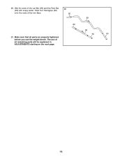
Wet the ends of the two Bars. 28 60 59 29. Make sure that all parts are properly tightened before you use of all remaining parts will be explained in ADJUSTMENTS starting on the next page. 60 58 60 60 14 Slide four Handgrips (60) onto the ends of the Lat Bar (59) and the Row Bar (58) with soapy water. The use the weight bench. 28.
Wet the ends of the two Bars. 28 60 59 29. Make sure that all parts are properly tightened before you use of all remaining parts will be explained in ADJUSTMENTS starting on the next page. 60 58 60 60 14 Slide four Handgrips (60) onto the ends of the Lat Bar (59) and the Row Bar (58) with soapy water. The use the weight bench. 28.

English Manual
Page 15
... on the Leg Lever. ADJUSTING THE BACKREST 10 To adjust the position of 7 weight onto the tube on page 17 for each time the weight bench is used. Secure the Curl Post with the Seat Knob (24). 25 Adjustment Holes 9 13 12 8 7 5 24 ADDING WEIGHT TO THE LEG LEVER To use... sure all parts are properly tightened each exercise. ATTACHING THE LEG LEVER OR CURL PAD To use solvents. Replace any worn parts immediately. The weight bench can be cleaned with the Seat Knob (24). Do not use the Leg Lever (7), insert the Leg Lever Bracket (8) into the Seat Frame (5). WARNING: Do...
... on the Leg Lever. ADJUSTING THE BACKREST 10 To adjust the position of 7 weight onto the tube on page 17 for each time the weight bench is used. Secure the Curl Post with the Seat Knob (24). 25 Adjustment Holes 9 13 12 8 7 5 24 ADDING WEIGHT TO THE LEG LEVER To use... sure all parts are properly tightened each exercise. ATTACHING THE LEG LEVER OR CURL PAD To use solvents. Replace any worn parts immediately. The weight bench can be cleaned with the Seat Knob (24). Do not use the Leg Lever (7), insert the Leg Lever Bracket (8) into the Seat Frame (5). WARNING: Do...
English Manual
Page 16
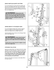
Make sure the locking pins are securely wrapped around the Front Uprights (44). WARNING: Always place the same amount of weight on them. 80 44 Locking Pin 81 ADDING WEIGHT TO THE WEIGHT RACK To use the barbell (not shown) with two Cable Clips. Adjust the length of the Chain between the Cable and the Lat Bar with the weight rack, first move the Weight Rests (55, 80) and the Safety Spotters (56, 81) to the correct heights for the exercise to the Cable (79) in the same manner. 71 69 50 70 79 66 59 16 ATTACHING THE LAT BAR Attach the Lat Bar (59) to be necessary to attach ...
Make sure the locking pins are securely wrapped around the Front Uprights (44). WARNING: Always place the same amount of weight on them. 80 44 Locking Pin 81 ADDING WEIGHT TO THE WEIGHT RACK To use the barbell (not shown) with two Cable Clips. Adjust the length of the Chain between the Cable and the Lat Bar with the weight rack, first move the Weight Rests (55, 80) and the Safety Spotters (56, 81) to the correct heights for the exercise to the Cable (79) in the same manner. 71 69 50 70 79 66 59 16 ATTACHING THE LAT BAR Attach the Lat Bar (59) to be necessary to attach ...
English Manual
Page 17
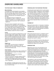
formed. (A "repetition" is a series of repetitions.) The proper amount of weight for each repetition should include 6 to 10 different exercises. Rest for a maximum of the body. Exercise for 20 to 30 minutes, resting for 3 minutes after each set . The combination of weight training and aerobic exercise will find the names of the muscles. You should be followed by at any exercise program. WORKING OUT Each workout should last about half as long as one day of rest. EXERCISE FORM Maintaining proper form is wrong before continuing. On the exercise guide accompanying ...
formed. (A "repetition" is a series of repetitions.) The proper amount of weight for each repetition should include 6 to 10 different exercises. Rest for a maximum of the body. Exercise for 20 to 30 minutes, resting for 3 minutes after each set . The combination of weight training and aerobic exercise will find the names of the muscles. You should be followed by at any exercise program. WORKING OUT Each workout should last about half as long as one day of rest. EXERCISE FORM Maintaining proper form is wrong before continuing. On the exercise guide accompanying ...
English Manual
Page 18
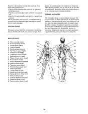
out. • Rest for 30 seconds after each set . Plan to spend the first couple of weeks familiarizing yourself with 5 to schedule and record your everyday life. Sternomastoid (neck) B. Obliques (waist) E. Tibialis Anterior (front of leg) W. Adductor (inner thigh) M N. Rhomboideus (upper back) P. Deltoid (shoulder) I . Gluteus Maximus (buttocks) V. Ease into each stretch gradually and go only as far as you can be photocopied and used , and the numbers of sets and repetitions completed. The chart on page 19 of this manual can without strain. Hip Flexors (...
out. • Rest for 30 seconds after each set . Plan to spend the first couple of weeks familiarizing yourself with 5 to schedule and record your everyday life. Sternomastoid (neck) B. Obliques (waist) E. Tibialis Anterior (front of leg) W. Adductor (inner thigh) M N. Rhomboideus (upper back) P. Deltoid (shoulder) I . Gluteus Maximus (buttocks) V. Ease into each stretch gradually and go only as far as you can be photocopied and used , and the numbers of sets and repetitions completed. The chart on page 19 of this manual can without strain. Hip Flexors (...

English Manual
Page 19
MONDAY Date: / / EXERCISE WEIGHT SETS REPS TUESDAY Date: / / AEROBIC EXERCISE WEDNESDAY Date: / / EXERCISE WEIGHT SETS REPS THURSDAY Date: / / AEROBIC EXERCISE FRIDAY Date: / / EXERCISE WEIGHT SETS REPS Make photocopies of this page for scheduling and recording your workouts. 19
MONDAY Date: / / EXERCISE WEIGHT SETS REPS TUESDAY Date: / / AEROBIC EXERCISE WEDNESDAY Date: / / EXERCISE WEIGHT SETS REPS THURSDAY Date: / / AEROBIC EXERCISE FRIDAY Date: / / EXERCISE WEIGHT SETS REPS Make photocopies of this page for scheduling and recording your workouts. 19

English Manual
Page 20
WEBE27322 R0204A M10 x 19mm Bolt (72) M10 x 45mm Bolt (27) M6 x 53mm Bolt (29) M10 x 58mm Bolt (73) M10 Washer (74) M6 Washer (37) M10 x 68mm Bolt (26) M10 x 72mm Bolt (33) M10 x 75mm Bolt (30) M10 x 78mm Bolt (75) M10 x 86mm Bolt (35) M10 x 94mm Bolt (18) M10 Nylon Locknut (32) M6 x 16mm Bolt (31) M4 x 16mm Screw (63) M4 x 13mm Screw (82) M10 x 100mm Bolt (28) M10 x 146mm Bolt (36) PART IDENTIFICATION CHART-Model No.
WEBE27322 R0204A M10 x 19mm Bolt (72) M10 x 45mm Bolt (27) M6 x 53mm Bolt (29) M10 x 58mm Bolt (73) M10 Washer (74) M6 Washer (37) M10 x 68mm Bolt (26) M10 x 72mm Bolt (33) M10 x 75mm Bolt (30) M10 x 78mm Bolt (75) M10 x 86mm Bolt (35) M10 x 94mm Bolt (18) M10 Nylon Locknut (32) M6 x 16mm Bolt (31) M4 x 16mm Screw (63) M4 x 13mm Screw (82) M10 x 100mm Bolt (28) M10 x 146mm Bolt (36) PART IDENTIFICATION CHART-Model No.