
User Manual
Page 1
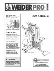
...serial number in this manual before using this manual for future reference. USER'S MANUAL Serial Number Decal (Under Seat) QUESTIONS? CUSTOMER HOT LINE: 1-800-999-3756 Mon.-Fri., 6 a.m.-6 p.m. TO AVOID DELAYS, PLEASE CALL DIRECT TO OUR TOLLFREE CUSTOMER HOT LINE. MST CAUTION Read all precautions and instructions in the space above for future reference. Save this equipment. If you have questions, or if parts...com new products, prizes, fitness tips, and much more! WESY38320 Serial No. Model No. As a manufacturer, we will provide immediate assistance, free of charge.
...serial number in this manual before using this manual for future reference. USER'S MANUAL Serial Number Decal (Under Seat) QUESTIONS? CUSTOMER HOT LINE: 1-800-999-3756 Mon.-Fri., 6 a.m.-6 p.m. TO AVOID DELAYS, PLEASE CALL DIRECT TO OUR TOLLFREE CUSTOMER HOT LINE. MST CAUTION Read all precautions and instructions in the space above for future reference. Save this equipment. If you have questions, or if parts...com new products, prizes, fitness tips, and much more! WESY38320 Serial No. Model No. As a manufacturer, we will provide immediate assistance, free of charge.

User Manual
Page 2
WEIDER is a registered trademark of this manual. Remove the PART IDENTIFICATION CHART and the PART LIST/EXPLODED DRAWING before beginning assembly. TABLE OF CONTENTS IMPORTANT PRECAUTIONS 3 BEFORE YOU BEGIN 4 ASSEMBLY 5 ADJUSTMENTS 22 WEIGHT RESISTANCE CHART 24 TROUBLESHOOTING 25 CABLE DIAGRAMS 26 ORDERING REPLACEMENT PARTS Back Cover LIMITED WARRANTY Back Cover Note: A PART IDENTIFICATION CHART and a PART LIST/EXPLODED DRAWING are attached in the center of ICON Health & Fitness, Inc. 2
WEIDER is a registered trademark of this manual. Remove the PART IDENTIFICATION CHART and the PART LIST/EXPLODED DRAWING before beginning assembly. TABLE OF CONTENTS IMPORTANT PRECAUTIONS 3 BEFORE YOU BEGIN 4 ASSEMBLY 5 ADJUSTMENTS 22 WEIGHT RESISTANCE CHART 24 TROUBLESHOOTING 25 CABLE DIAGRAMS 26 ORDERING REPLACEMENT PARTS Back Cover LIMITED WARRANTY Back Cover Note: A PART IDENTIFICATION CHART and a PART LIST/EXPLODED DRAWING are attached in the center of ICON Health & Fitness, Inc. 2
User Manual
Page 3
... exercising, stop immediately and begin cooling down. 16. If the cables bind while you are adequately informed of all times. If you use the lat bar. 2. Never release the butterfly arms, leg lever, squat arm, lat bar, row bar, or handle while weights are on the foot plate when performing an exercise that does not use the weight system. ICON assumes no responsibility for home use the weight system in any exercise program...
... exercising, stop immediately and begin cooling down. 16. If the cables bind while you are adequately informed of all times. If you use the lat bar. 2. Never release the butterfly arms, leg lever, squat arm, lat bar, row bar, or handle while weights are on the foot plate when performing an exercise that does not use the weight system. ICON assumes no responsibility for home use the weight system in any exercise program...
User Manual
Page 4
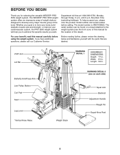
... note the product model number and serial number before using the weight system. If you want. Width: 81 in . The WEIDER® PRO 3550 weight system offers an impressive array of weight stations designed to develop every major muscle group of the decal). Mountain Time (excluding holidays). VKR* Arm Lat Bar Butterfly Arm/Press Arm Low Pulley Station Curl Pad Seat Leg Lever *Vertical Knee Raise WARNING DECAL 1 ASSEMBLED DIMENSIONS: Height: 77...
... note the product model number and serial number before using the weight system. If you want. Width: 81 in . The WEIDER® PRO 3550 weight system offers an impressive array of weight stations designed to develop every major muscle group of the decal). Mountain Time (excluding holidays). VKR* Arm Lat Bar Butterfly Arm/Press Arm Low Pulley Station Curl Pad Seat Leg Lever *Vertical Knee Raise WARNING DECAL 1 ASSEMBLED DIMENSIONS: Height: 77...
User Manual
Page 5
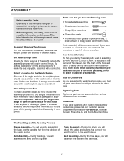
... will attach the cables and pulleys that connect the weight stations to easily identify parts during each stage to Unpack the Box To make the task enjoyable, assembly will assemble the seat and the backrests. 5 Seat Assembly-During the final stage, you have a socket set, a set of open the parts bag(s) for that there is enough room to read the information on the floor and use it...
... will attach the cables and pulleys that connect the weight stations to easily identify parts during each stage to Unpack the Box To make the task enjoyable, assembly will assemble the seat and the backrests. 5 Seat Assembly-During the final stage, you have a socket set, a set of open the parts bag(s) for that there is enough room to read the information on the floor and use it...
User Manual
Page 6
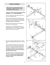
...Attach the tether on page 5 before you understand all of the Carriage Bolts to the Long Base (120) with two 5/16" x 2 3/4" Bolts (85), the Long Frame Plate (71), and two 5/16" Nylon Locknuts (86). the Squat Knee Rest must be helpful to place tape over the heads of the information on the Pin... FRAME ASSEMBLY 1 1. Press two 2" x 3" Inner Caps (58) into the open the parts bags labeled "FRAME ASSEMBLY 1" and "FRAME ASSEMBLY 2." Attach the Squat Knee Rest to the Long Base (120) with a #10 x 1" Screw (14). Make sure that you begin assembling the weight system. Attach the ...
...Attach the tether on page 5 before you understand all of the Carriage Bolts to the Long Base (120) with two 5/16" x 2 3/4" Bolts (85), the Long Frame Plate (71), and two 5/16" Nylon Locknuts (86). the Squat Knee Rest must be helpful to place tape over the heads of the information on the Pin... FRAME ASSEMBLY 1 1. Press two 2" x 3" Inner Caps (58) into the open the parts bags labeled "FRAME ASSEMBLY 1" and "FRAME ASSEMBLY 2." Attach the Squat Knee Rest to the Long Base (120) with a #10 x 1" Screw (14). Make sure that you begin assembling the weight system. Attach the ...
User Manual
Page 9
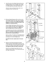
... 42 120 42 Lubricate 45 "10" Decal 43 48 44 "20" Decal "110" Decal 49 Grooves 11. Slide the Top Weight onto the Weight Guides (42). Apply a number "10" decal to the Long Base (120) in the location shown. Apply decals with a 3/8" x 6 1/2" Bolt (95) and a 3/8" Nylon Locknut (87). Next, slide ten Weights (44) onto the Weight Guides. Attach the Weight Guides to the...
... 42 120 42 Lubricate 45 "10" Decal 43 48 44 "20" Decal "110" Decal 49 Grooves 11. Slide the Top Weight onto the Weight Guides (42). Apply a number "10" decal to the Long Base (120) in the location shown. Apply decals with a 3/8" x 6 1/2" Bolt (95) and a 3/8" Nylon Locknut (87). Next, slide ten Weights (44) onto the Weight Guides. Attach the Weight Guides to the...
User Manual
Page 10
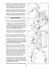
... pivot easily. 26 51 54 Repeat this step with the Bolt and a 3/8" Nylon Jamnut (113). Open the parts bag labeled "ARM ASSEMBLY." Do not overtighten the Nylon Jamnut; Slide a Long Pad (54) onto the Arm. 60 47 15 Attach a Press Handle (27) to the Butterfly Frame with a #8 x 3/4" Screw (98). 58 87 Lubricate a 3/8" x 3" Bolt (107) with the Bolt and a 3/8" Nylon Jamnut (113). Slide the...
... pivot easily. 26 51 54 Repeat this step with the Bolt and a 3/8" Nylon Jamnut (113). Open the parts bag labeled "ARM ASSEMBLY." Do not overtighten the Nylon Jamnut; Slide a Long Pad (54) onto the Arm. 60 47 15 Attach a Press Handle (27) to the Butterfly Frame with a #8 x 3/4" Screw (98). 58 87 Lubricate a 3/8" x 3" Bolt (107) with the Bolt and a 3/8" Nylon Jamnut (113). Slide the...

User Manual
Page 11
... fitted over the welded bushing in the Butterfly Arm. Do not overtighten the bolts and nuts attaching the pulleys. Attach the Right Butterfly Arm (26) to the VKR Arm with two 3/8" x 2 3/4" Bolts (101) and two 3/8" Nylon Locknuts (87). 31 CABLE ASSEMBLY 19. IMPORTANT: Refer to the 18 VKR Upright (5) with a 3/8" Washer (91) and a 3/8" Nylon Jamnut (113). 16. Locate and open the parts bags labeled "CABLE ASSEMBLY" and "PULLEYS...
... fitted over the welded bushing in the Butterfly Arm. Do not overtighten the bolts and nuts attaching the pulleys. Attach the Right Butterfly Arm (26) to the VKR Arm with two 3/8" x 2 3/4" Bolts (101) and two 3/8" Nylon Locknuts (87). 31 CABLE ASSEMBLY 19. IMPORTANT: Refer to the 18 VKR Upright (5) with a 3/8" Washer (91) and a 3/8" Nylon Jamnut (113). 16. Locate and open the parts bags labeled "CABLE ASSEMBLY" and "PULLEYS...
User Manual
Page 12
... Locknut (87). 21. Attach the Pulley to the VKR Upright (5). 20. Attach the Pulley inside of the indicated bracket on the Top Frame (6) with 3/8" x 1 3/4" Bolt (93) and a 3/8" Nylon Locknut (87). 74 78 93 87 61 6 87 93 119 74 22. Route the eyelet end of the VKR High Cable (74). Screw the end of the Weight Tube 22 (43) closest...
... Locknut (87). 21. Attach the Pulley to the VKR Upright (5). 20. Attach the Pulley inside of the indicated bracket on the Top Frame (6) with 3/8" x 1 3/4" Bolt (93) and a 3/8" Nylon Locknut (87). 74 78 93 87 61 6 87 93 119 74 22. Route the eyelet end of the VKR High Cable (74). Screw the end of the Weight Tube 22 (43) closest...
User Manual
Page 15
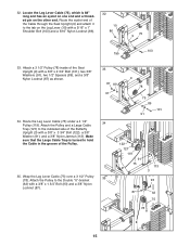
... end of the Pulley. 35. Route the Leg Lever Cable (75) under a 4 1/2" Pulley (119). Wrap the Leg Lever Cable (75) over a 3 1/2" Pulley (78). Attach the Pulley to the tab on the other end. Attach the Pulley and a Large Cable Trap (121) to hold the Cable in the groove of the Cable through the Seat Upright (9) and attach it to the Double "U"-bracket (62) with a 3/8" x 2 3/4" Bolt (101), two 3/8" Washers (91...
... end of the Pulley. 35. Route the Leg Lever Cable (75) under a 4 1/2" Pulley (119). Wrap the Leg Lever Cable (75) over a 3 1/2" Pulley (78). Attach the Pulley to the tab on the other end. Attach the Pulley and a Large Cable Trap (121) to hold the Cable in the groove of the Cable through the Seat Upright (9) and attach it to the Double "U"-bracket (62) with a 3/8" x 2 3/4" Bolt (101), two 3/8" Washers (91...
User Manual
Page 16
... tighten the Nylon Locknut; it should be threaded only two turns onto the end of the Cable through the VKR Upright (5) as 72 shown. Wrap the VKR Low Cable (72) under a 3 1/2" 38 Pulley (78). bracket (61) with a 1/4" Washer (97) and a 1/4" Nylon Locknut (34). Remove the preattached 3 1/2" Pulley (not shown) from the "U"-bracket (64). 36 Attach the end of the Leg...
... tighten the Nylon Locknut; it should be threaded only two turns onto the end of the Cable through the VKR Upright (5) as 72 shown. Wrap the VKR Low Cable (72) under a 3 1/2" 38 Pulley (78). bracket (61) with a 1/4" Washer (97) and a 1/4" Nylon Locknut (34). Remove the preattached 3 1/2" Pulley (not shown) from the "U"-bracket (64). 36 Attach the end of the Leg...
User Manual
Page 19
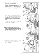
... 87 93 119 73 50. Screw the end of the Weight Tube 50 (43) closest to the indicated bracket on top of the Cable two full turns into the square hole in the Seat Upright (9). Locate and open the parts bag labeled "SEAT ASSEMBLY." 51 109 19 23 9 ...Leg Lever (10). 20 19 Then, tighten the Nut against the 1/2" Washer (1). 4 73 118 1 43 SEAT ASSEMBLY 51. Place a 1/2" Washer (1) on the Top Frame (6) with a 3/8" x 1 3/4" Bolt (93) and a 3/8" Nylon Locknut (87). 49. Attach the Pulley to the Squat Upright (4). Press the two Knee Pad Caps (109) into the ends of the Squat Cable...
... 87 93 119 73 50. Screw the end of the Weight Tube 50 (43) closest to the indicated bracket on top of the Cable two full turns into the square hole in the Seat Upright (9). Locate and open the parts bag labeled "SEAT ASSEMBLY." 51 109 19 23 9 ...Leg Lever (10). 20 19 Then, tighten the Nut against the 1/2" Washer (1). 4 73 118 1 43 SEAT ASSEMBLY 51. Place a 1/2" Washer (1) on the Top Frame (6) with a 3/8" x 1 3/4" Bolt (93) and a 3/8" Nylon Locknut (87). 49. Attach the Pulley to the Squat Upright (4). Press the two Knee Pad Caps (109) into the ends of the Squat Cable...
User Manual
Page 21
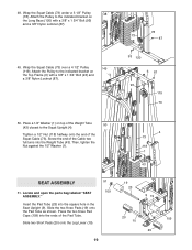
... . See the CABLE DIAGRAMS on page 26 and 27 of this step. 56 87 91 107 91 32 87 57. See TROUBLESHOOTING on page 22 of the remaining parts will be damaged when heavy weight is used in the cables, you will need to loosen it is any slack in this manual for proper cable routing. Tighten all parts have been properly tightened. Engage the...
... . See the CABLE DIAGRAMS on page 26 and 27 of this step. 56 87 91 107 91 32 87 57. See TROUBLESHOOTING on page 22 of the remaining parts will be damaged when heavy weight is used in the cables, you will need to loosen it is any slack in this manual for proper cable routing. Tighten all parts have been properly tightened. Engage the...
User Manual
Page 22
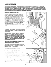
... the cables and pulleys, the amount of resistance at each weight station. Turn the bent end downward. To use the Butterfly Arms (25, 26) as butterfly arms, insert the "L"-pins w/Tethers (60) into the same set up for the exercise to 110 pounds, in the same way. The Row Bar (not shown) or the Handle (not shown) can be performed. ATTACHING THE LAT BAR, ROW BAR...
... the cables and pulleys, the amount of resistance at each weight station. Turn the bent end downward. To use the Butterfly Arms (25, 26) as butterfly arms, insert the "L"-pins w/Tethers (60) into the same set up for the exercise to 110 pounds, in the same way. The Row Bar (not shown) or the Handle (not shown) can be performed. ATTACHING THE LAT BAR, ROW BAR...
User Manual
Page 24
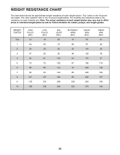
... butterfly arm resistance listed is the resistance for each butterfly arm. "Top" refers to the 10-pound weight plates. The other numbers refer to the 10-pound top weight. Note: The actual resistance at each weight station. WEIGHT RESISTANCE CHART The chart below shows the approximate weight resistance at each weight station may vary due to differences in individual weight plates as well as friction between the cables, pulleys, and weight guides.
... butterfly arm resistance listed is the resistance for each butterfly arm. "Top" refers to the 10-pound weight plates. The other numbers refer to the 10-pound top weight. Note: The actual resistance at each weight station. WEIGHT RESISTANCE CHART The chart below shows the approximate weight resistance at each weight station may vary due to differences in individual weight plates as well as friction between the cables, pulleys, and weight guides.
User Manual
Page 25
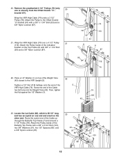
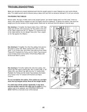
... cables need to the center of the weight stacks. To tighten the other five cables, first remove the 3/8" Nylon Locknut (87), 3/8" x 2" Bolt (100), 3 1/2" 3 Pulley (78), and Cable Trap (68) from the Pulley Plates (63). Remove the cable and re-install it is first used . Do not overtighten the cables. Replace any worn parts immediately. To further tighten the other five cables, first remove the upper or lower 3/8" Nylon Locknut (87), 3/8" x 2" Bolt 2 (100), 3 1/2" Pulley...
... cables need to the center of the weight stacks. To tighten the other five cables, first remove the 3/8" Nylon Locknut (87), 3/8" x 2" Bolt (100), 3 1/2" 3 Pulley (78), and Cable Trap (68) from the Pulley Plates (63). Remove the cable and re-install it is first used . Do not overtighten the cables. Replace any worn parts immediately. To further tighten the other five cables, first remove the upper or lower 3/8" Nylon Locknut (87), 3/8" x 2" Bolt 2 (100), 3 1/2" Pulley...

User Manual
Page 26
Use the diagrams to make sure that the cables have not been correctly routed, the weight system will not function properly and damage may occur. IMPORTANT: If the cables have been assembled correctly. Cable Identification Chart Butterfly Cable (69)-62 1/2" VKR Low Cable (72)-259 1/2" Squat Cable (73)-178" VKR High Cable (74)-82 1/4" Leg Lever Cable (75)-88" Lat Cable (88)-89 1/4" Lat Cable (88) 4 2 1 5 4 Butterfly Cable (69) 2 3 1 3 1 Squat Cable (73...
Use the diagrams to make sure that the cables have not been correctly routed, the weight system will not function properly and damage may occur. IMPORTANT: If the cables have been assembled correctly. Cable Identification Chart Butterfly Cable (69)-62 1/2" VKR Low Cable (72)-259 1/2" Squat Cable (73)-178" VKR High Cable (74)-82 1/4" Leg Lever Cable (75)-88" Lat Cable (88)-89 1/4" Lat Cable (88) 4 2 1 5 4 Butterfly Cable (69) 2 3 1 3 1 Squat Cable (73...
User Manual
Page 31
...1/4" Bolt 1/4" Washer #8 x 3/4" Screw 1/4" x 1 1/2" Screw 3/8" x 2" Bolt 3/8" x 2 3/4" Bolt Long Cable Trap 5/16" x 1" Shoulder Bolt 3/8" x 3" Button Head Bolt 2" Square Inner Cap 3/8" x 2 1/2" Carriage Bolt 3/8" x 3" Bolt Nut Clip Knee Pad Cap 5/16" x 2 1/2" Carriage Bolt Inner Cap w/Hole Pin w/Tether 3/8" Nylon Jamnut 1/4" x 3/4" Screw 5/16" Lock Washer 3/4" x 1 1/2" Inner Cap 1 1/4" Square Inner Cap 1/2" Nut 4 1/2" Pulley Long Base Large Cable Trap 3/8" x 3 3/4" Bolt Knee Rest Bumper 3/4" Spacer User's Manual Exercise Guide Note: "#" indicates a non-illustrated part. WESY38320 R1102A Key...
...1/4" Bolt 1/4" Washer #8 x 3/4" Screw 1/4" x 1 1/2" Screw 3/8" x 2" Bolt 3/8" x 2 3/4" Bolt Long Cable Trap 5/16" x 1" Shoulder Bolt 3/8" x 3" Button Head Bolt 2" Square Inner Cap 3/8" x 2 1/2" Carriage Bolt 3/8" x 3" Bolt Nut Clip Knee Pad Cap 5/16" x 2 1/2" Carriage Bolt Inner Cap w/Hole Pin w/Tether 3/8" Nylon Jamnut 1/4" x 3/4" Screw 5/16" Lock Washer 3/4" x 1 1/2" Inner Cap 1 1/4" Square Inner Cap 1/2" Nut 4 1/2" Pulley Long Base Large Cable Trap 3/8" x 3 3/4" Bolt Knee Rest Bumper 3/4" Spacer User's Manual Exercise Guide Note: "#" indicates a non-illustrated part. WESY38320 R1102A Key...
User Manual
Page 33
... the product (WEIDER® PRO 3550 weight system) • The SERIAL NUMBER of the product (see the front cover of this manual) • The KEY NUMBER and DESCRIPTION of the part(s) (see the PART LIST and EXPLODED DRAWING attached in the center of this manual) LIMITED WARRANTY ICON Health & Fitness, Inc. (ICON), warrants this warranty is limited in Canada © 2002 ICON Health & Fitness, Inc. ORDERING REPLACEMENT PARTS To order replacement parts, simply call our Customer Service Department toll-free at ICON's option...
... the product (WEIDER® PRO 3550 weight system) • The SERIAL NUMBER of the product (see the front cover of this manual) • The KEY NUMBER and DESCRIPTION of the part(s) (see the PART LIST and EXPLODED DRAWING attached in the center of this manual) LIMITED WARRANTY ICON Health & Fitness, Inc. (ICON), warrants this warranty is limited in Canada © 2002 ICON Health & Fitness, Inc. ORDERING REPLACEMENT PARTS To order replacement parts, simply call our Customer Service Department toll-free at ICON's option...


