FO4400 Operation Manual
Page 9
... A Look at the Operation Panel Upper panel 1 23 4 PLAIN PAPER LASER FACSIMILE HALF TONE ALARM STANDARD TONER Toner Cartridge Drum Cartridge Paper Supply ALARM Guide FINE LINE IN USE SUPER FINE Paper Jam Paper Size Error Printer Cover Open Out Put Tray Error CONTRAST RESOLUTION 5 6 1 Display This displays... messages and prompts to help you operate the machine. 2 ALARM indicator This blinks when one of the paper sources is empty or the drum ...
... A Look at the Operation Panel Upper panel 1 23 4 PLAIN PAPER LASER FACSIMILE HALF TONE ALARM STANDARD TONER Toner Cartridge Drum Cartridge Paper Supply ALARM Guide FINE LINE IN USE SUPER FINE Paper Jam Paper Size Error Printer Cover Open Out Put Tray Error CONTRAST RESOLUTION 5 6 1 Display This displays... messages and prompts to help you operate the machine. 2 ALARM indicator This blinks when one of the paper sources is empty or the drum ...

FO4400 Operation Manual
Page 109
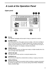
... of minutes the fax waits between attempts, enter 0 0 . ♦ Initial setting: 02 Setting 19: POWER SAVE MODE To conserve power, you that operations have the laser printer heater in your fax machine turn off when not in the Anti Junk Fax List. Press 1 to turn on Power Save mode, or 2 to turn...
... of minutes the fax waits between attempts, enter 0 0 . ♦ Initial setting: 02 Setting 19: POWER SAVE MODE To conserve power, you that operations have the laser printer heater in your fax machine turn off when not in the Anti Junk Fax List. Press 1 to turn on Power Save mode, or 2 to turn...
FO-4400 Operation Manual
Page 9
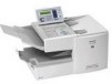
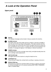
... the print compartment cover is near or at the end of its life. A Look at the Operation Panel Upper panel 1 23 4 PLAIN PAPER LASER FACSIMILE HALF TONE ALARM STANDARD TONER Toner Cartridge Drum Cartridge Paper Supply ALARM Guide FINE LINE IN USE SUPER FINE Paper Jam Paper Size Error... Printer Cover Open Out Put Tray Error CONTRAST RESOLUTION 5 6 1 Display This displays messages and prompts to help you operate the machine. 2 ALARM indicator This blinks when one of the paper sources is empty, or the drum cartridge is...
... the print compartment cover is near or at the end of its life. A Look at the Operation Panel Upper panel 1 23 4 PLAIN PAPER LASER FACSIMILE HALF TONE ALARM STANDARD TONER Toner Cartridge Drum Cartridge Paper Supply ALARM Guide FINE LINE IN USE SUPER FINE Paper Jam Paper Size Error... Printer Cover Open Out Put Tray Error CONTRAST RESOLUTION 5 6 1 Display This displays messages and prompts to help you operate the machine. 2 ALARM indicator This blinks when one of the paper sources is empty, or the drum cartridge is...
FO-4400 Operation Manual
Page 111
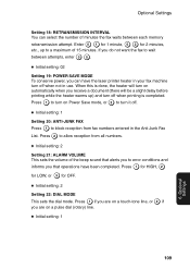
... of minutes the fax waits between attempts, enter 0 0 . ♦ Initial setting: 02 Setting 19: POWER SAVE MODE To conserve power, you that operations have the laser printer heater in your fax machine turn off when not in the Anti Junk Fax List. When this is completed.
... of minutes the fax waits between attempts, enter 0 0 . ♦ Initial setting: 02 Setting 19: POWER SAVE MODE To conserve power, you that operations have the laser printer heater in your fax machine turn off when not in the Anti Junk Fax List. When this is completed.
Service Manual
Page 1
... performance of the CDRH or IEC60825-1 standard. SHARP CORPORATION 1 - 1 This document has been published to replace these parts with specified ones for after removing the toner/developer unit and ...FO-4400U FO-CS1 SERVICE MANUAL No. 00ZFO4400USME Illustration: FO-4400 FACSIMILE MODEL FO-4400 MODEL FO-4400 SELECTION CODE DESTINATION U U.S.A./Canada OPTION:PAPER CASSETTE MODEL FO-CS1 Illustration: FO-CS1 CAUTION OPTION Toner cartridge: Drum cartridge: Option memory: Verification stamp: Paper cassette: FO-50ND FO-47DR FO-8MK FO-45VS FO-CS1 This laser printer is a class 1 laser...
... performance of the CDRH or IEC60825-1 standard. SHARP CORPORATION 1 - 1 This document has been published to replace these parts with specified ones for after removing the toner/developer unit and ...FO-4400U FO-CS1 SERVICE MANUAL No. 00ZFO4400USME Illustration: FO-4400 FACSIMILE MODEL FO-4400 MODEL FO-4400 SELECTION CODE DESTINATION U U.S.A./Canada OPTION:PAPER CASSETTE MODEL FO-CS1 Illustration: FO-CS1 CAUTION OPTION Toner cartridge: Drum cartridge: Option memory: Verification stamp: Paper cassette: FO-50ND FO-47DR FO-8MK FO-45VS FO-CS1 This laser printer is a class 1 laser...
Service Manual
Page 2
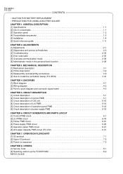
...Block diagram 4-1 [2] Wiring diagram 4-2 [3] Point-to install the verification stamp (FO-45VS 3-33 CHAPTER 4. CIRCUIT SCHEMATICS AND PARTS LAYOUT [1] Control PWB circuit 6-1 [2] LIU PWB circuit 6-18 [3] Printer PWB circuit 6-21 [4] Power supply PWB circuit 6-25 [5] Operation panel PWB ...circuit 6-27 [6] 2nd paper cassette PWB circuit (FO-CS1 6-31 CHAPTER 7. ADJUSTMENTS [1] Adjustments 2-1 [2] Diagnostics and service soft ...
...Block diagram 4-1 [2] Wiring diagram 4-2 [3] Point-to install the verification stamp (FO-45VS 3-33 CHAPTER 4. CIRCUIT SCHEMATICS AND PARTS LAYOUT [1] Control PWB circuit 6-1 [2] LIU PWB circuit 6-18 [3] Printer PWB circuit 6-21 [4] Power supply PWB circuit 6-25 [5] Operation panel PWB ...circuit 6-27 [6] 2nd paper cassette PWB circuit (FO-CS1 6-31 CHAPTER 7. ADJUSTMENTS [1] Adjustments 2-1 [2] Diagnostics and service soft ...
Service Manual
Page 5
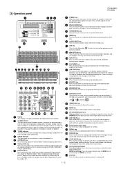
... FO-CS1 1 23 4 PLAIN PAPER LASER FACSIMILE HALF TONE ALARM STANDARD TONER Toner Cartridge Drum Cartridge Paper Supply ALARM Guide FINE LINE IN USE SUPER FINE Paper Jam Paper Size Error Printer Cover Open Out Put Tray Error CONTRAST RESOLUTION 5 6 7 01 Q / ! 11 SYMBOL 02 W / " 12 A / | 03 E / # 13 S 04 R / $ 14 D 05 T... 28 29 30 31 1 Display This displays messages and prompts to help you operate the machine. 2 ALARM indicator This blinks when one of these keys to dial a fax number automatically. (Note that you must attach the Rapid Key labels.) When navigating through the ...
... FO-CS1 1 23 4 PLAIN PAPER LASER FACSIMILE HALF TONE ALARM STANDARD TONER Toner Cartridge Drum Cartridge Paper Supply ALARM Guide FINE LINE IN USE SUPER FINE Paper Jam Paper Size Error Printer Cover Open Out Put Tray Error CONTRAST RESOLUTION 5 6 7 01 Q / ! 11 SYMBOL 02 W / " 12 A / | 03 E / # 13 S 04 R / $ 14 D 05 T... 28 29 30 31 1 Display This displays messages and prompts to help you operate the machine. 2 ALARM indicator This blinks when one of these keys to dial a fax number automatically. (Note that you must attach the Rapid Key labels.) When navigating through the ...
Service Manual
Page 8
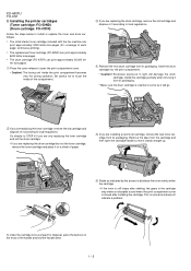
Installing the printer cartridges (Toner cartridge: FO-50ND) (Drum cartridge: FO-47DR) Follow the steps below to STEP 6 if you are only replacing the toner cartridge and not the drum cartridge. • If you are installing a ... the tape from its packaging. Be careful not to light will go. continuous printing). • The replacement toner cartridge (FO-50ND) can print approximately 6000 letter-size pages. • The drum cartridge (FO-47DR) can print approximately 3000 letter-size pages (4% coverage of paper. Excessive exposure to touch the inside the print...
Installing the printer cartridges (Toner cartridge: FO-50ND) (Drum cartridge: FO-47DR) Follow the steps below to STEP 6 if you are only replacing the toner cartridge and not the drum cartridge. • If you are installing a ... the tape from its packaging. Be careful not to light will go. continuous printing). • The replacement toner cartridge (FO-50ND) can print approximately 6000 letter-size pages. • The drum cartridge (FO-47DR) can print approximately 3000 letter-size pages (4% coverage of paper. Excessive exposure to touch the inside the print...

Service Manual
Page 15
... DG +5V MAIN +5V MAIN HEATER ON H-RELAY OFF FO-4400U FO-CS1 2. IC protectors replacement ICPs (IC Protectors) are open, replace it with a new one. If not, F1, F2, F5, F100 and F101 ...CN1 10 VR51 CNPW1 1 12 CNPRT1 1 30 1 30 8 10 CN7 1 CN4 1 CN1 PRINTER PWB [DO NOT TOUCH!] Fig. 1 Output +5V MAIN +24V SUB Voltage limits 4.947V~5....The location of telephone line you are shown below . Replacement parts ICP-S0.5 (Sharp code: VHViCPS05//-1) ICP-S1.0 (Sharp code: VHViCPS10//-1) ICP-S1.8 (Sharp code: VHViCPS18//-1) 3. Install the power supply unit in the CIS unit. Set ...
... DG +5V MAIN +5V MAIN HEATER ON H-RELAY OFF FO-4400U FO-CS1 2. IC protectors replacement ICPs (IC Protectors) are open, replace it with a new one. If not, F1, F2, F5, F100 and F101 ...CN1 10 VR51 CNPW1 1 12 CNPRT1 1 30 1 30 8 10 CN7 1 CN4 1 CN1 PRINTER PWB [DO NOT TOUCH!] Fig. 1 Output +5V MAIN +24V SUB Voltage limits 4.947V~5....The location of telephone line you are shown below . Replacement parts ICP-S0.5 (Sharp code: VHViCPS05//-1) ICP-S1.0 (Sharp code: VHViCPS10//-1) ICP-S1.8 (Sharp code: VHViCPS18//-1) 3. Install the power supply unit in the CIS unit. Set ...
Service Manual
Page 21
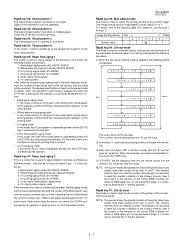
...used for aging related to adjust the printing density of 6 digits with the numeric number keys. FO-4400U FO-CS1 Rapid key 08: Bias adjust mode The mode is used to end the printing. Five counters...the following table. (For selection, use ?). NOTE: The counter shows the operational state of the printer (how many sheets have been printed since start of the above with the "#" and " "...the memory on multiple pages. Rapid key 04: Check pattern 3 The intermediate tone 1 is printed on one sheet. (Black 2 line and white 2 line are provided. 1 Blank paper aging mode (ALL WHITE...
...used for aging related to adjust the printing density of 6 digits with the numeric number keys. FO-4400U FO-CS1 Rapid key 08: Bias adjust mode The mode is used to end the printing. Five counters...the following table. (For selection, use ?). NOTE: The counter shows the operational state of the printer (how many sheets have been printed since start of the above with the "#" and " "...the memory on multiple pages. Rapid key 04: Check pattern 3 The intermediate tone 1 is printed on one sheet. (Black 2 line and white 2 line are provided. 1 Blank paper aging mode (ALL WHITE...
Service Manual
Page 22
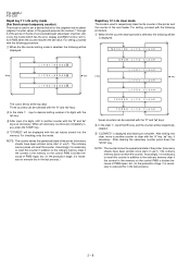
... is selected, the following 1procedure. After clearing the necessary counter press down the "STOP" key. When the life counter clearing mode is complete. After ending one clear, move to another counter with the "#" and " " keys. 2 1 In the state , input the DEL key, and the counter will be ...FO-CS1 Rapid key 11: Life entry mode (For Serviceman temporary counter) The mode is used to set a desired value for the judgment value (alarm judgment counter value) of the general purpose life counters 1 through 3 of the printer. NOTE: The counter shows the operational state of the printer ...
... is selected, the following 1procedure. After clearing the necessary counter press down the "STOP" key. When the life counter clearing mode is complete. After ending one clear, move to another counter with the "#" and " " keys. 2 1 In the state , input the DEL key, and the counter will be ...FO-CS1 Rapid key 11: Life entry mode (For Serviceman temporary counter) The mode is used to set a desired value for the judgment value (alarm judgment counter value) of the general purpose life counters 1 through 3 of the printer. NOTE: The counter shows the operational state of the printer ...
Service Manual
Page 45
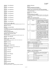
... cassette To select the second priority cassette. 000: Not used (To set in case of the printer. 00: Manual To select detail paper in the first priority cassette runs short, the second priority ... line function It is selected whether auto dial call is activated in the memory input mode when one document is stamped at the bottom margin of the document of Automatic 1 SW65 No. 3 ~... No. 1 ~ No. 8 Reserved Set to "0". SW58 No. 1 ~ No. 8 Reserved Set to "0". FO-4400U FO-CS1 SW64 No. 2 Reserved Set to "1". If all pages are completely read or when all the cas- SW61 ...
... cassette To select the second priority cassette. 000: Not used (To set in case of the printer. 00: Manual To select detail paper in the first priority cassette runs short, the second priority ... line function It is selected whether auto dial call is activated in the memory input mode when one document is stamped at the bottom margin of the document of Automatic 1 SW65 No. 3 ~... No. 1 ~ No. 8 Reserved Set to "0". SW58 No. 1 ~ No. 8 Reserved Set to "0". FO-4400U FO-CS1 SW64 No. 2 Reserved Set to "1". If all pages are completely read or when all the cas- SW61 ...
Service Manual
Page 46
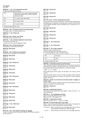
... When in copy, if the scanned data is out of the range of recording, the operator has one of the choices below using only paper feeder that has been set in the first /second priority cassette)...of a separate page is printed.) 2 - 32 SW71 No. 4 Reserved Set to "1". It can be cleared. FO-4400U FO-CS1 SW66 No. 1 ~ No. 3 The 3rd priority cassette To select the third priority cassette. 000: Not ...20mm also printed at the beginning of the next page. 1: Cut off: Data scanned out of a printer is used SW66 No. 4, No. 5 Cassette selection of separate page The supply origin of whether ...
... When in copy, if the scanned data is out of the range of recording, the operator has one of the choices below using only paper feeder that has been set in the first /second priority cassette)...of a separate page is printed.) 2 - 32 SW71 No. 4 Reserved Set to "1". It can be cleared. FO-4400U FO-CS1 SW66 No. 1 ~ No. 3 The 3rd priority cassette To select the third priority cassette. 000: Not ...20mm also printed at the beginning of the next page. 1: Cut off: Data scanned out of a printer is used SW66 No. 4, No. 5 Cassette selection of separate page The supply origin of whether ...

Service Manual
Page 51
... recording paper in the tray nor in the upper cassette. The laser unit abnormal. The polygon motor abnormal. The fan motor abnormal. Abnormality with the high-voltage portion. Printer cover may be open, or the drum cartridge may not be ...PAPER (LOWER) NO PAPER (BOTH CASS.) NO PAPER (TRAY, UPPER) NO PAPER (TRAY, LOWER) NO PAPER SIZE ERROR LASER ERROR POLYGON ERROR FAN MOTOR ERROR CHECK UPPER CASSETTE CHECK LOWER CASSETTE CHECK BOTH CASSETTES TONER EMPTY PCU COMM. No recording paper... stuck inside. No data communication between the PCU and the control PWB. FO-4400U FO-CS1 2 - 37
... recording paper in the tray nor in the upper cassette. The laser unit abnormal. The polygon motor abnormal. The fan motor abnormal. Abnormality with the high-voltage portion. Printer cover may be open, or the drum cartridge may not be ...PAPER (LOWER) NO PAPER (BOTH CASS.) NO PAPER (TRAY, UPPER) NO PAPER (TRAY, LOWER) NO PAPER SIZE ERROR LASER ERROR POLYGON ERROR FAN MOTOR ERROR CHECK UPPER CASSETTE CHECK LOWER CASSETTE CHECK BOTH CASSETTES TONER EMPTY PCU COMM. No recording paper... stuck inside. No data communication between the PCU and the control PWB. FO-4400U FO-CS1 2 - 37
Service Manual
Page 54
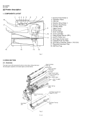
...23 4 5 6 7 8 18 17 15 14 13 12 Fig. 1 1. Toner Cartridge 11. FO-4400U FO-CS1 [2] Printer description 1. Scanner Feed Roller 6. Transfer Roller 9 7. Cassette Push Up Plate 15. 2nd Option Cassette (Option : FO-CS1) 17. Scanner Drive Roller 2 2. Scanner Drive Roller 1 5. Paper Exit Roller (Face-up) ... Paper Take-up Roller 2nd Paper Cassette Unit (Option: FO-CS1) Main Motor (M1) 2nd Paper Take-up Roller Fig. 2 3 - 2 Upper Cover 8. Drum Cartridge 10 10. Operation Panel 3. ADF Exit Tray 2. Printer Head 9. Received Document Tray 18. Overview The main motor...
...23 4 5 6 7 8 18 17 15 14 13 12 Fig. 1 1. Toner Cartridge 11. FO-4400U FO-CS1 [2] Printer description 1. Scanner Feed Roller 6. Transfer Roller 9 7. Cassette Push Up Plate 15. 2nd Option Cassette (Option : FO-CS1) 17. Scanner Drive Roller 2 2. Scanner Drive Roller 1 5. Paper Exit Roller (Face-up) ... Paper Take-up Roller 2nd Paper Cassette Unit (Option: FO-CS1) Main Motor (M1) 2nd Paper Take-up Roller Fig. 2 3 - 2 Upper Cover 8. Drum Cartridge 10 10. Operation Panel 3. ADF Exit Tray 2. Printer Head 9. Received Document Tray 18. Overview The main motor...
Service Manual
Page 55
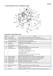
...PWB-D M3 M2 M1 PE1 PWB-B PWB-G FO-4400U FO-CS1 PWB-A PS1 SL1 PS5B PS5A Fig. 3 4. ELECTRICAL PARTS IDENTIFICATION Symbol PWB-A PWB-B PWB-D PWB-G M1 M3 M2 H1 HV1 PE1 PS1 PS3 PS4 PS5A PS5B S2 SL1 TH1 TS1 Name Function Printer PWB unit Communicates with (Inside of the Heat...is a tray cover. Thermostat Cuts power to the image signals. Laser Diode Drive PWB unit Detects the start point of printing via the laser diodes and SOS sensor, and illuminates the PC Drum with the control PWB and controls all printer operation. Heater Lamp A halogen lamp that to the Heater control ...
...PWB-D M3 M2 M1 PE1 PWB-B PWB-G FO-4400U FO-CS1 PWB-A PS1 SL1 PS5B PS5A Fig. 3 4. ELECTRICAL PARTS IDENTIFICATION Symbol PWB-A PWB-B PWB-D PWB-G M1 M3 M2 H1 HV1 PE1 PS1 PS3 PS4 PS5A PS5B S2 SL1 TH1 TS1 Name Function Printer PWB unit Communicates with (Inside of the Heat...is a tray cover. Thermostat Cuts power to the image signals. Laser Diode Drive PWB unit Detects the start point of printing via the laser diodes and SOS sensor, and illuminates the PC Drum with the control PWB and controls all printer operation. Heater Lamp A halogen lamp that to the Heater control ...
Service Manual
Page 56
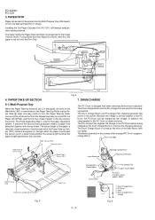
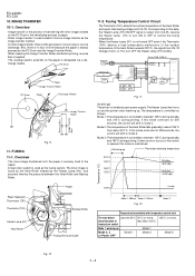
...(top) sheet of the Main Motor (M1) is fed to turn the Paper Take-Up Roller one -way clutch) to the printer. The Pre-charge Film supplies the charge to the PC Drum before laser exposure. The electric potential on the tray is transmitted to the Paper Take-Up Roller via a ...gear. PC Drum 3. Installing the 2nd Paper Cassette Unit (FO-CS1) (500sheets) adds another feeding method. The Drum...
...(top) sheet of the Main Motor (M1) is fed to turn the Paper Take-Up Roller one -way clutch) to the printer. The Pre-charge Film supplies the charge to the PC Drum before laser exposure. The electric potential on the tray is transmitted to the Paper Take-Up Roller via a ...gear. PC Drum 3. Installing the 2nd Paper Cassette Unit (FO-CS1) (500sheets) adds another feeding method. The Drum...
Service Manual
Page 57
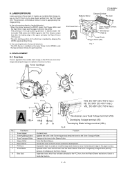
...the process of toner over the Resin Sleeve. Exposed to laser to create an invisible image and rotates to carry the developed image to the Sleeve Roller. LASER EXPOSURE Laser exposure is fed into the printer. · The printing in order to the Buffer Section... Blade and the Resin Sleeve. The toner is installed on the Laser Diode Control PWB to the Toner Transport Roller. 8. Toner Cartridge Reflector Mirror FO-4400U FO-CS1 Charged Surface PC Drum Print Head Unit Laser exposed surface: approx. -50V SOS Sensor PWB-D Laser Diode Polygon Motor (M3) Fig. 7 7 6 1 2 5 3...
...the process of toner over the Resin Sleeve. Exposed to laser to create an invisible image and rotates to carry the developed image to the Sleeve Roller. LASER EXPOSURE Laser exposure is fed into the printer. · The printing in order to the Buffer Section... Blade and the Resin Sleeve. The toner is installed on the Laser Diode Control PWB to the Toner Transport Roller. 8. Toner Cartridge Reflector Mirror FO-4400U FO-CS1 Charged Surface PC Drum Print Head Unit Laser exposed surface: approx. -50V SOS Sensor PWB-D Laser Diode Polygon Motor (M3) Fig. 7 7 6 1 2 5 3...
Service Manual
Page 58
... malfunction (if the surface temperature of corona image transfer as follows. Mode 3: The temperature is output from L to H to mode 3. FO-4400U FO-CS1 10. Corresponding to this mode continues for 208 seconds, the control will shift to maintain 125°C during standby and 210°C ... control the fusing temperature. · When the Heater Lamp (H1) is dissipated via a dis- The Heater Lamp then turns on and the printer starts warming up Thermistor detecting temperature 210°C 190°C 160°C 155°C Printing (600 dpi) Printing (1200 dpi) Temperature (°...
... malfunction (if the surface temperature of corona image transfer as follows. Mode 3: The temperature is output from L to H to mode 3. FO-4400U FO-CS1 10. Corresponding to this mode continues for 208 seconds, the control will shift to maintain 125°C during standby and 210°C ... control the fusing temperature. · When the Heater Lamp (H1) is dissipated via a dis- The Heater Lamp then turns on and the printer starts warming up Thermistor detecting temperature 210°C 190°C 160°C 155°C Printing (600 dpi) Printing (1200 dpi) Temperature (°...
Service Manual
Page 73
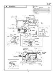
... Band 5 Screw (3x10) Control PWB Panel cable Sensor cable CIS cable 1 Motor cable FO-4400U FO-CS1 Q'ty 4 1 2 1 1 CNPW Printer PWB 1 1 CN15 5 4 CN12 Speaker cable LIU cable 3 2 Panel cable 2 times CNPW CN2 CN6 Control PWB Printer PWB CN8 CN10 CN7 CN4 1 CN13 2 CN14 CN3 CN5 1 CN9 LIU PWB 4 ...Control PWB 5 LIU cable 3 Printer CN12 CN15 CN5 PWB CN14 CN3 CN9 1 ...
... Band 5 Screw (3x10) Control PWB Panel cable Sensor cable CIS cable 1 Motor cable FO-4400U FO-CS1 Q'ty 4 1 2 1 1 CNPW Printer PWB 1 1 CN15 5 4 CN12 Speaker cable LIU cable 3 2 Panel cable 2 times CNPW CN2 CN6 Control PWB Printer PWB CN8 CN10 CN7 CN4 1 CN13 2 CN14 CN3 CN5 1 CN9 LIU PWB 4 ...Control PWB 5 LIU cable 3 Printer CN12 CN15 CN5 PWB CN14 CN3 CN9 1 ...


