Instructions
Page 4
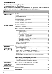
... are for VN-C655 with V.Networks Setup Tool 28 Registering the Connected Camera with V.Networks Controller 30 Operations (V.Networks Controller) Others Step 3 Setting with V.Networks Controller Starting Up V.Networks Controller 31 Function Settings with V.Networks Controller 32 Step 4 Operations with V.Networks Controller Operations with V.Networks Controller 34 ... Step 2 Setting the Network Installing the Software 23 Setting the PC's IP Address for Windows XP 24 Setting the PC's IP Address for Windows 2000 26 Setting the IP Address for VN-C655U.) Before beginning to operate...
... are for VN-C655 with V.Networks Setup Tool 28 Registering the Connected Camera with V.Networks Controller 30 Operations (V.Networks Controller) Others Step 3 Setting with V.Networks Controller Starting Up V.Networks Controller 31 Function Settings with V.Networks Controller 32 Step 4 Operations with V.Networks Controller Operations with V.Networks Controller 34 ... Step 2 Setting the Network Installing the Software 23 Setting the PC's IP Address for Windows XP 24 Setting the PC's IP Address for Windows 2000 26 Setting the IP Address for VN-C655U.) Before beginning to operate...
Instructions
Page 13
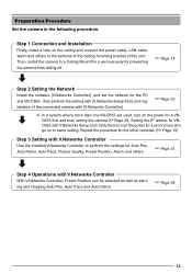
...perform the settings for the PC and VN-C655. Repeat the procedure for the other cameras. (☞ Page 15) Step 3 Setting with V.Networks Controller Use the installed V.Networks Controller to same setting. Step 1 ...VN- Then, install the camera to the terminal of the ceiling-mounting bracket of the connected camera with V.Networks Controller With V.Networks Controller, Preset Position can be selected as well as starting and stopping Auto Pan, Auto Trace and Auto Patrol. ☞ Page 34 13 Also perform the setting with V.Networks Setup tool). C655 with [V.Networks Setup Tool...
...perform the settings for the PC and VN-C655. Repeat the procedure for the other cameras. (☞ Page 15) Step 3 Setting with V.Networks Controller Use the installed V.Networks Controller to same setting. Step 1 ...VN- Then, install the camera to the terminal of the ceiling-mounting bracket of the connected camera with V.Networks Controller With V.Networks Controller, Preset Position can be selected as well as starting and stopping Auto Pan, Auto Trace and Auto Patrol. ☞ Page 34 13 Also perform the setting with V.Networks Setup tool). C655 with [V.Networks Setup Tool...
Instructions
Page 15
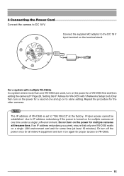
..., ensure that only one VN-C655 exists on for multiple cameras at the factory. Repeat the procedure for some time (at the same time. Connect the supplied AC adaptor to DC 18 V. For a system with V.Networks Setup tool). 3 Connecting the Power Cord Connect the camera to the DC 18 V... input terminal on the power for a VN-C655 first and then setting the camera (☞Page 28, Setting the IP Adress for VN-C655 with multiple VN-C655s In a system where more than one VN-C655 are used,...
..., ensure that only one VN-C655 exists on for multiple cameras at the factory. Repeat the procedure for some time (at the same time. Connect the supplied AC adaptor to DC 18 V. For a system with V.Networks Setup tool). 3 Connecting the Power Cord Connect the camera to the DC 18 V... input terminal on the power for a VN-C655 first and then setting the camera (☞Page 28, Setting the IP Adress for VN-C655 with multiple VN-C655s In a system where more than one VN-C655 are used,...
Instructions
Page 19
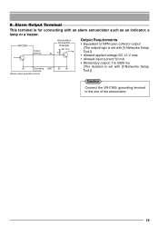
... Terminal This terminal is set with [V.Networks Setup Tool.]) Caution Connect the VN-C655 grounding terminal to 5000 ms (The duration is for connecting with [V.Networks Setup Tool.]) • Allowed applied voltage: DC 12 V max. • Allowed input current: 50 mA • Momentary output: 1 to the one of the annunciator. 19 VN-C655 Output terminal Annunciator Connection Example...
... Terminal This terminal is set with [V.Networks Setup Tool.]) Caution Connect the VN-C655 grounding terminal to 5000 ms (The duration is for connecting with [V.Networks Setup Tool.]) • Allowed applied voltage: DC 12 V max. • Allowed input current: 50 mA • Momentary output: 1 to the one of the annunciator. 19 VN-C655 Output terminal Annunciator Connection Example...
Instructions
Page 23
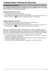
... is created in [Programs] of the Windows [Start] menu. [V.Networks Controller] is displayed in [V.Networks]. If success, the message "DllRegistreServer in the [JVC] folder. 2. Installing V.Networks Setup Tool 1. Installing V.Networks Controller 1. If the installation is successfully executed, the [V.Networks] icon is created in [Programs] of the Windows [Start] menu. [vn-c655u Setup Tool] is displayed in the following procedure. If DirectX9.x or...
... is created in [Programs] of the Windows [Start] menu. [V.Networks Controller] is displayed in [V.Networks]. If success, the message "DllRegistreServer in the [JVC] folder. 2. Installing V.Networks Setup Tool 1. Installing V.Networks Controller 1. If the installation is successfully executed, the [V.Networks] icon is created in [Programs] of the Windows [Start] menu. [vn-c655u Setup Tool] is displayed in the following procedure. If DirectX9.x or...
Instructions
Page 28
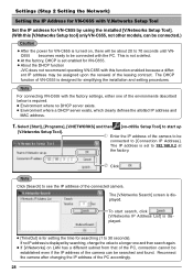
...], [V.NETWORKS] and then [vn-c655u Setup Tool] to start search, click . [V.Networks IP Address List] is for setting the time for searching (1 to see the IP address of the camera can be connected.) Caution ● After the power for VN-C655 is designed for VN-C655. ● About the DHCP function JVC does not recommend operating VN-C655 with this [V.Networks Setup tool] only VN...
...], [V.NETWORKS] and then [vn-c655u Setup Tool] to start search, click . [V.Networks IP Address List] is for setting the time for searching (1 to see the IP address of the camera can be connected.) Caution ● After the power for VN-C655 is designed for VN-C655. ● About the DHCP function JVC does not recommend operating VN-C655 with this [V.Networks Setup tool] only VN...
Instructions
Page 29
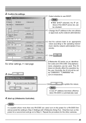
... IP address to use DHCP. Click . [V.Networks ID] works as "CAM00001," "CAM00002" etc. (0 to VN-C655. Start up [V.Networks Controller]. Only then turn on to Step 3 Settings with V.Networks Setup Tool. This ID does not directly affect the operation by the network administrator. Note A new IP address becomes effective when VN-C655 is automatically reset. Note ● With...
... IP address to use DHCP. Click . [V.Networks ID] works as "CAM00001," "CAM00002" etc. (0 to VN-C655. Start up [V.Networks Controller]. Only then turn on to Step 3 Settings with V.Networks Setup Tool. This ID does not directly affect the operation by the network administrator. Note A new IP address becomes effective when VN-C655 is automatically reset. Note ● With...
Instructions
Page 36
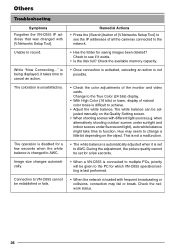
...24 bits) display. • With High Color (16 bits) or lower, display of all the cameras connected to the network. • Has the folder for a few seconds. • When a VN-C655 is connected to multiple PCs, priority will be established or fails. The operation is disabled for ...the Quality Setting screen. • When shooting scenes with [V.Networks Setup Tool]. During the adjustment, the picture quality cannot be set to VN-C655 cannot be given to the PC for which VN-C655 operation/setting is last performed. • When the network is being displayed, it exists. • Is the ...
...24 bits) display. • With High Color (16 bits) or lower, display of all the cameras connected to the network. • Has the folder for a few seconds. • When a VN-C655 is connected to multiple PCs, priority will be established or fails. The operation is disabled for ...the Quality Setting screen. • When shooting scenes with [V.Networks Setup Tool]. During the adjustment, the picture quality cannot be set to VN-C655 cannot be given to the PC for which VN-C655 operation/setting is last performed. • When the network is being displayed, it exists. • Is the ...

