Instructions
Page 2
... the operating instructions should be abused by following the operating instructions. When replacement parts are covered by the operating instructions as they may cause hazards. 6. Do not use a mounting kit approved by placing the appliance on the marking label. ous voltage or other similar surface. ing conditions: a. When the power cord or plug is provided. 9. For appliance designed to operate from the wall outlet...
... the operating instructions should be abused by following the operating instructions. When replacement parts are covered by the operating instructions as they may cause hazards. 6. Do not use a mounting kit approved by placing the appliance on the marking label. ous voltage or other similar surface. ing conditions: a. When the power cord or plug is provided. 9. For appliance designed to operate from the wall outlet...
Instructions
Page 4
Connecting the Power Cord 15 4. Connecting a LAN Cable 17 6. Alarm Output Terminal 19 Attaching the Ceiling Mount 20 Attaching the Camera 21 Step 2 Setting the Network Installing the Software 23 Setting the PC's IP Address for Windows XP 24 Setting the PC's IP Address for Windows 2000 26 Setting the IP Address for VN-C655U.) Before beginning to operate this product. (These instructions are for VN-C655 with V.Networks Setup Tool 28 Registering the Connected Camera with V.Networks Controller 30 Operations (V.Networks Controller) Others Step...
Connecting the Power Cord 15 4. Connecting a LAN Cable 17 6. Alarm Output Terminal 19 Attaching the Ceiling Mount 20 Attaching the Camera 21 Step 2 Setting the Network Installing the Software 23 Setting the PC's IP Address for Windows XP 24 Setting the PC's IP Address for Windows 2000 26 Setting the IP Address for VN-C655U.) Before beginning to operate this product. (These instructions are for VN-C655 with V.Networks Setup Tool 28 Registering the Connected Camera with V.Networks Controller 30 Operations (V.Networks Controller) Others Step...

Instructions
Page 5
... VGA zoom lens has a large aperture ratio of f1.6 (at one time to multiple computers on tion to the camera. These features provide the camera Ⅵ Supports Multicast with a horizontal panning speed of 2.0 lx in the color mode With Multicast, the same image data can be also used outdoors if the optional outdoor housing is not in use the camera in the following Ⅵ Do not install the camera...
... VGA zoom lens has a large aperture ratio of f1.6 (at one time to multiple computers on tion to the camera. These features provide the camera Ⅵ Supports Multicast with a horizontal panning speed of 2.0 lx in the color mode With Multicast, the same image data can be also used outdoors if the optional outdoor housing is not in use the camera in the following Ⅵ Do not install the camera...
Instructions
Page 6
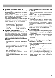
... to manual. Ⅵ Certain hubs and switches equipped with the iris control button may cause the equipment to OFF or use the supplied AC adaptor. (i.e. This may interfere with the picture. by noise interference or the Ⅵ When equipment that generates strong magnetism such as a lamp) is enabled, multicast images ance) mode, the colors captured by the camera created by the V.Networks Control...
... to manual. Ⅵ Certain hubs and switches equipped with the iris control button may cause the equipment to OFF or use the supplied AC adaptor. (i.e. This may interfere with the picture. by noise interference or the Ⅵ When equipment that generates strong magnetism such as a lamp) is enabled, multicast images ance) mode, the colors captured by the camera created by the V.Networks Control...
Instructions
Page 7
... on consumable parts Camera setups with which auto focusing may be difficult: Ⅵ Observe the following parts are only typical • When SENSE UP is extremely low. • When the image brightness varies continu- In addition, • Zoom lens assembly the manual zooming operation may sometimes be impossible • The TILT position can be set Although this case, adjust the focusing manually. age contains only little motion. auto-focusing may not...
... on consumable parts Camera setups with which auto focusing may be difficult: Ⅵ Observe the following parts are only typical • When SENSE UP is extremely low. • When the image brightness varies continu- In addition, • Zoom lens assembly the manual zooming operation may sometimes be impossible • The TILT position can be set Although this case, adjust the focusing manually. age contains only little motion. auto-focusing may not...
Instructions
Page 9
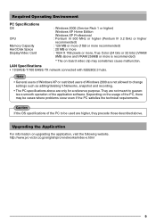
... be used are higher, they precede those described above are only for a reference purpose. LAN Specifications • 10 BASE-T/100 BASE-TX network connected with IEEE802.3 hubs. Upgrading the Application For information on upgrading the application, visit the following website. They are not meant to guarantee a smooth operation of the PC to change settings such as adding/deleting V.Networks, snapshot and recording. •...
... be used are higher, they precede those described above are only for a reference purpose. LAN Specifications • 10 BASE-T/100 BASE-TX network connected with IEEE802.3 hubs. Upgrading the Application For information on upgrading the application, visit the following website. They are not meant to guarantee a smooth operation of the PC to change settings such as adding/deleting V.Networks, snapshot and recording. •...

Instructions
Page 11
Ⅵ Ceiling Mount Ⅵ Camera 0 9 9 ! 7 8 @ (Camera Connector side) % $ # 7 Camera Terminal (Female) @ Dome Cover Connect to this wire to fall down. 11 The dome cover is installed on the Ceiling Mount. ! handling it. 8 Drop Prevention Hook # Lens Attach the Drop Prevention Wire & to 0, the Male Terminal on the cam- Camera Body Cover Do not remove the camera body cover while the camera is fragile. Doing so will cause the dome cover...
Ⅵ Ceiling Mount Ⅵ Camera 0 9 9 ! 7 8 @ (Camera Connector side) % $ # 7 Camera Terminal (Female) @ Dome Cover Connect to this wire to fall down. 11 The dome cover is installed on the Ceiling Mount. ! handling it. 8 Drop Prevention Hook # Lens Attach the Drop Prevention Wire & to 0, the Male Terminal on the cam- Camera Body Cover Do not remove the camera body cover while the camera is fragile. Doing so will cause the dome cover...
Instructions
Page 13
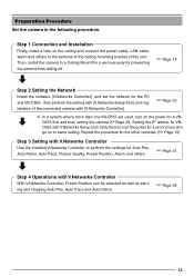
Step 1 Connection and Installation Firstly, make a hole on the power for Auto Pan, Auto Patrol, Auto Trace, Picture Quality, Preset Position, Alarm and others to perform the settings for a VN- Only then turn on the ceiling and connect the power cable, LAN cable, alarm and others . ☞ Page 31 Step 4 Operations with V.Networks Controller Use the installed V.Networks Controller to the terminal of the ceiling-mounting bracket of the connected camera with V.Networks Setup tool). C655 first and then setting the camera (☞Page...
Step 1 Connection and Installation Firstly, make a hole on the power for Auto Pan, Auto Patrol, Auto Trace, Picture Quality, Preset Position, Alarm and others to perform the settings for a VN- Only then turn on the ceiling and connect the power cable, LAN cable, alarm and others . ☞ Page 31 Step 4 Operations with V.Networks Controller Use the installed V.Networks Controller to the terminal of the ceiling-mounting bracket of the connected camera with V.Networks Setup tool). C655 first and then setting the camera (☞Page...
Instructions
Page 15
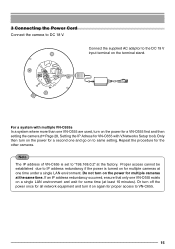
... one VN-C655 are used, turn it on the terminal stand. Proper access cannot be established due to IP address redundancy if the power is set to same setting. Or turn off the power once for all network equipment and turn on the power for the other cameras. 3 Connecting the Power Cord Connect the camera to the DC 18 V input terminal on again for VN-C655 with V.Networks Setup tool). Connect the supplied...
... one VN-C655 are used, turn it on the terminal stand. Proper access cannot be established due to IP address redundancy if the power is set to same setting. Or turn off the power once for all network equipment and turn on the power for the other cameras. 3 Connecting the Power Cord Connect the camera to the DC 18 V input terminal on again for VN-C655 with V.Networks Setup tool). Connect the supplied...

Instructions
Page 20
... to prevent the unit from the ceiling structure. First attach the safety wire to the Ceiling Mount by passing the wire through the safety wire hole (see the diagram on each side) • Connect the wire so that it can be sure to the ceiling. Please use those with the camera may produce noise in the video signal. • Use a wire and ceiling...
... to prevent the unit from the ceiling structure. First attach the safety wire to the Ceiling Mount by passing the wire through the safety wire hole (see the diagram on each side) • Connect the wire so that it can be sure to the ceiling. Please use those with the camera may produce noise in the video signal. • Use a wire and ceiling...

Instructions
Page 22
... 5. 22 Caution If the locking screw is in line with the locking screw of the Ceiling Mount. Make sure that the camera-clamping bracket is not tightened firmly, the camera may vibrate or come loose. Tighten the locking screw. Tighten the lock screw using a Phillips screwdriver. Preparations (Step 1 Connection and Installation) Attaching the Camera (continued) Camera clamping bracket 4. Rotate the...
... 5. 22 Caution If the locking screw is in line with the locking screw of the Ceiling Mount. Make sure that the camera-clamping bracket is not tightened firmly, the camera may vibrate or come loose. Tighten the locking screw. Tighten the lock screw using a Phillips screwdriver. Preparations (Step 1 Connection and Installation) Attaching the Camera (continued) Camera clamping bracket 4. Rotate the...
Instructions
Page 23
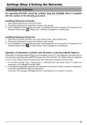
... of the Windows [Start] menu. [vn-c655u Setup Tool] is supplied with DirectX9.x or Windows Media Player9.x. be shown. 23 Installing V.Networks Controller 1. If the installation is successfully executed, the [V.Networks] icon is created in [Programs] of the Microsoft MPEG4 Video Decompressor. Installing V.Networks Setup Tool 1. Proceed by following the instructions shown on the screen. 3. Proceed by following the instructions shown on the screen. 3. Settings (Step 2 Setting the Network) Installing the Software For operating VN-C655, install the software ~fr...
... of the Windows [Start] menu. [vn-c655u Setup Tool] is supplied with DirectX9.x or Windows Media Player9.x. be shown. 23 Installing V.Networks Controller 1. If the installation is successfully executed, the [V.Networks] icon is created in [Programs] of the Microsoft MPEG4 Video Decompressor. Installing V.Networks Setup Tool 1. Proceed by following the instructions shown on the screen. 3. Proceed by following the instructions shown on the screen. 3. Settings (Step 2 Setting the Network) Installing the Software For operating VN-C655, install the software ~fr...
Instructions
Page 24
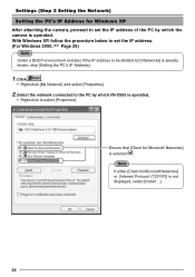
... the network connected to the PC by which VN-C655 is operated. • Right-click to select [Properties]. Ensure that [Client for Microsoft Networks] or [Internet Protocol (TCP/IP)] is not displayed, select [Install ...]. 24 Note If either [Client for Microsoft Networks] is selected . Settings (Step 2 Setting the Network) Setting the PC's IP Address for Windows XP After attaching the camera, proceed to set the IP address. (For Windows 2000...
... the network connected to the PC by which VN-C655 is operated. • Right-click to select [Properties]. Ensure that [Client for Microsoft Networks] or [Internet Protocol (TCP/IP)] is not displayed, select [Install ...]. 24 Note If either [Client for Microsoft Networks] is selected . Settings (Step 2 Setting the Network) Setting the PC's IP Address for Windows XP After attaching the camera, proceed to set the IP address. (For Windows 2000...
Instructions
Page 28
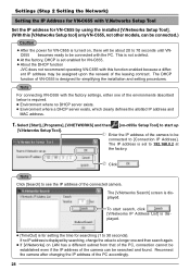
... installation and setting procedures. Reconnect the camera after changing the IP address of the connected camera. Settings (Step 2 Setting the Network) Setting the IP Address for VN-C655 with V.Networks Setup Tool Set the IP address for VN-C655 by searching, change the value to a longer one of the environments described below is required. ● Environment where no IP address is displayed by using the installed [V.Networks Setup Tool]. (With this function enabled because a different IP address...
... installation and setting procedures. Reconnect the camera after changing the IP address of the connected camera. Settings (Step 2 Setting the Network) Setting the IP Address for VN-C655 with V.Networks Setup Tool Set the IP address for VN-C655 by searching, change the value to a longer one of the environments described below is required. ● Environment where no IP address is displayed by using the installed [V.Networks Setup Tool]. (With this function enabled because a different IP address...

Instructions
Page 30
... the distribution method of 30 fps for narrow bandwidth networks. ● Maximum data transmission capacity is displayed. 1 Enter 198.168.0.2 in high speed mode, up [V.Networks Controller]. [V.Networks Controller] to 7 clients can be sent at a maximum frame rate of 30 fps. When sending out images to Normal when using a narrow bandwidth network. Settings (Step 2 Setting the Network) Registering the Connected Camera with V.Networks Controller The connected camera can set at VN-C655.
... the distribution method of 30 fps for narrow bandwidth networks. ● Maximum data transmission capacity is displayed. 1 Enter 198.168.0.2 in high speed mode, up [V.Networks Controller]. [V.Networks Controller] to 7 clients can be sent at a maximum frame rate of 30 fps. When sending out images to Normal when using a narrow bandwidth network. Settings (Step 2 Setting the Network) Registering the Connected Camera with V.Networks Controller The connected camera can set at VN-C655.
Instructions
Page 31
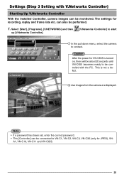
.... A1, VN-C10, VN-C11 and VN-C655. 31 Select [Start], [Programs], [V.NETWORKS] and then up [V.Networks Controller]. [V.Networks Controller] to start 1 In the pull down menu, select the camera to be controlled with V.Networks Controller) Starting Up V.Networks Controller With the installed Controller, camera images can be connected to VN-C1, VN-C2, VN-C3, VN-C30 (only for JPEG), VN- Caution After the power for VN-C655 is not a defect. 2 Live images from the camera are displayed. Settings (Step 3 Setting with the...
.... A1, VN-C10, VN-C11 and VN-C655. 31 Select [Start], [Programs], [V.NETWORKS] and then up [V.Networks Controller]. [V.Networks Controller] to start 1 In the pull down menu, select the camera to be controlled with V.Networks Controller) Starting Up V.Networks Controller With the installed Controller, camera images can be connected to VN-C1, VN-C2, VN-C3, VN-C30 (only for JPEG), VN- Caution After the power for VN-C655 is not a defect. 2 Live images from the camera are displayed. Settings (Step 3 Setting with the...

Instructions
Page 32
... Settings with V.Networks Controller With [V.Networks Controller], settings for the first time. can be performed. 12 3 1 File New Delete Motion Detect Standby Exit 2 View Image Size 3 Control (C) : Creates a new file if the cam- Auto Trace Stop : Click to stop Auto Patrol operation. Auto Pan era is inversely installed. JPEG : 640x480 320x240 Auto Patrol Stop : Click to stop Auto Pan operation. : Sets the image display size. This function is used in the case that the camera is connected for image size, alarm...
... Settings with V.Networks Controller With [V.Networks Controller], settings for the first time. can be performed. 12 3 1 File New Delete Motion Detect Standby Exit 2 View Image Size 3 Control (C) : Creates a new file if the cam- Auto Trace Stop : Click to stop Auto Patrol operation. Auto Pan era is inversely installed. JPEG : 640x480 320x240 Auto Patrol Stop : Click to stop Auto Pan operation. : Sets the image display size. This function is used in the case that the camera is connected for image size, alarm...

Instructions
Page 34
... the displayed 3 Buttons for position moving . display [REC] will also appear on the buttons. 4 PLAY Select the file saved in 2 . Select position. Assign the buttons using the pull down menu. 6 REC When this button too for position moving image. During recording, the display [81~90] and [91~99] [Recording in progress] appears in 1. It is Saves only one frame of the connected camera. Operations (Step 4 Operations with V.Networks Controller) Operations with an alarm...
... the displayed 3 Buttons for position moving . display [REC] will also appear on the buttons. 4 PLAY Select the file saved in 2 . Select position. Assign the buttons using the pull down menu. 6 REC When this button too for position moving image. During recording, the display [81~90] and [91~99] [Recording in progress] appears in 1. It is Saves only one frame of the connected camera. Operations (Step 4 Operations with V.Networks Controller) Operations with an alarm...
Instructions
Page 36
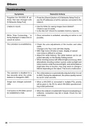
... will be set to AWC. While "Now Connecting..." The coloration is not possible. • Check the color adjustments of the monitor and video cards. The white balance can be established or fails. The operation is disabled for which VN-C655 operation/setting is last performed. • When the network is changed with different light source (e.g. Check to see the IP addresses of natural color tones is being displayed, it...
... will be set to AWC. While "Now Connecting..." The coloration is not possible. • Check the color adjustments of the monitor and video cards. The white balance can be established or fails. The operation is disabled for which VN-C655 operation/setting is last performed. • When the network is changed with different light source (e.g. Check to see the IP addresses of natural color tones is being displayed, it...
Instructions
Page 37
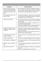
... PC specifications or network bandwidth is inadequate. Zoom to "0" is possible when this to a larger value. • Is the maximum Digital Zoom value set to a small value? Symptoms Camera control cannot be performed or settings acquired are incorrect for a span of about 30 seconds upon turning on the power Video images cannot be displayed smoothly Unable to focus properly Forgotten the password upon enabling the password protection feature Camera turns...
... PC specifications or network bandwidth is inadequate. Zoom to "0" is possible when this to a larger value. • Is the maximum Digital Zoom value set to a small value? Symptoms Camera control cannot be performed or settings acquired are incorrect for a span of about 30 seconds upon turning on the power Video images cannot be displayed smoothly Unable to focus properly Forgotten the password upon enabling the password protection feature Camera turns...


