Instruction Manual
Page 1
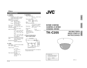
...° (V) Angle adjustment range: Horizontal: 120° Vertical: +80°, -50° Tilt: ±15° φ4-3/32 (103.5) • Design and specifications are subject to 40°C) Dimensions: Approx. 156 mm diam- E-16 DOME CAMERA CAMÉRA À DÔME CÁMARA DOMO TK-C205 For Customer Use: Enter below the Serial No. INSTRUCTIONS MODE D'EMPLOI INSTRUCCIONES...
...° (V) Angle adjustment range: Horizontal: 120° Vertical: +80°, -50° Tilt: ±15° φ4-3/32 (103.5) • Design and specifications are subject to 40°C) Dimensions: Approx. 156 mm diam- E-16 DOME CAMERA CAMÉRA À DÔME CÁMARA DOMO TK-C205 For Customer Use: Enter below the Serial No. INSTRUCTIONS MODE D'EMPLOI INSTRUCCIONES...
Instruction Manual
Page 2
... and openings in installation such as they may cause hazards. 6. ance should be sure the service technician has used replacement parts specified by the manufacturer, or sold with a 3-wire grounding type plug (a plug having a third (grounding) pin). This appliance system is provided. 9. If you are covered by the operating instructions as improper adjustment of power supplied to replace your dealer or local power company. c. All...
... and openings in installation such as they may cause hazards. 6. ance should be sure the service technician has used replacement parts specified by the manufacturer, or sold with a 3-wire grounding type plug (a plug having a third (grounding) pin). This appliance system is provided. 9. If you are covered by the operating instructions as improper adjustment of power supplied to replace your dealer or local power company. c. All...
Instruction Manual
Page 3
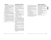
NO USER-SERVICEABLE PARTS INSIDE.REFER SERVICING TO QUALIFIED SERVICE PERSONNEL. Thank you for purchasing this instruction book are for TK-C205U and TK-C205E) CONTENTS Features ...4 Operating Precautions ...4 Safety Precautions ...5 Names and Operations of Parts Camera Body ...6 Body Surface ...6 Body Underside ...8 Installation and connection System diagram ...9 About Connection Cables 10 Mounting the Camera to the Ceiling 11 Connection for USA This device complies with Canadian ICES-003. Changes or modifications...
NO USER-SERVICEABLE PARTS INSIDE.REFER SERVICING TO QUALIFIED SERVICE PERSONNEL. Thank you for purchasing this instruction book are for TK-C205U and TK-C205E) CONTENTS Features ...4 Operating Precautions ...4 Safety Precautions ...5 Names and Operations of Parts Camera Body ...6 Body Surface ...6 Body Underside ...8 Installation and connection System diagram ...9 About Connection Cables 10 Mounting the Camera to the Ceiling 11 Connection for USA This device complies with Canadian ICES-003. Changes or modifications...
Instruction Manual
Page 4
... V power supply. This is used in the ATW mode, the recorded colors may have vertical lines (smear) or blur (blooming) at its mount. • The unit is to be sure to perform a test recording in order to confirm that a normal recording is dropped because of incomplete installation due to not observing the installation instructions correctly. Please contact your hand, contamination of this camera are used outdoors...
... V power supply. This is used in the ATW mode, the recorded colors may have vertical lines (smear) or blur (blooming) at its mount. • The unit is to be sure to perform a test recording in order to confirm that a normal recording is dropped because of incomplete installation due to not observing the installation instructions correctly. Please contact your hand, contamination of this camera are used outdoors...
Instruction Manual
Page 5
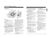
...] Auto-gain control switch When the brightness of the lens. When the 10 [WHT.BAL/PHASE] switch is set this switch to "ON" will become easier to view. (Default setting: OFF) 8 [AUTO/MANU] Auto/manual selection switch For selecting whether to "OFF" when making LEVEL adjustments. 3 MONITOR terminal (RCA pin) For connecting a monitor when determining camera angle, etc. (High impedance) 4 Horizontal LOCK screw When adjusting the camera angles horizontal rotation, this button...
...] Auto-gain control switch When the brightness of the lens. When the 10 [WHT.BAL/PHASE] switch is set this switch to "ON" will become easier to view. (Default setting: OFF) 8 [AUTO/MANU] Auto/manual selection switch For selecting whether to "OFF" when making LEVEL adjustments. 3 MONITOR terminal (RCA pin) For connecting a monitor when determining camera angle, etc. (High impedance) 4 Horizontal LOCK screw When adjusting the camera angles horizontal rotation, this button...
Instruction Manual
Page 6
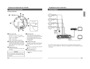
... drop prevention wire. E-8 Installation and connection System diagram Camera 1 Video signal Power Camera 2 Video signal Power Camera 3 Video signal Power Camera 4 Video signal Power Time Lapse VCR REC STOP/EJECT REC CHECK PAUSE/ REVERSE STILL PLAY REW FF VIDEO CASSETTE RECORDER COUNT/ CLOCK MENU SHIFT/TRACKING RESET /CANCEL TIME MODE TIMER REC SET/V.LOCK AL/PL RESET SR-L910E OPERATE OPE. MONITOR OUTPUT 1 MONITOR • Turn OFF the power supply to all equipment to be used before making connections. • Read the Instruction Manual for each...
... drop prevention wire. E-8 Installation and connection System diagram Camera 1 Video signal Power Camera 2 Video signal Power Camera 3 Video signal Power Camera 4 Video signal Power Time Lapse VCR REC STOP/EJECT REC CHECK PAUSE/ REVERSE STILL PLAY REW FF VIDEO CASSETTE RECORDER COUNT/ CLOCK MENU SHIFT/TRACKING RESET /CANCEL TIME MODE TIMER REC SET/V.LOCK AL/PL RESET SR-L910E OPERATE OPE. MONITOR OUTPUT 1 MONITOR • Turn OFF the power supply to all equipment to be used before making connections. • Read the Instruction Manual for each...
Instruction Manual
Page 7
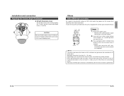
... connection errors or a cable disconnection, we recommend the use a wiring cable for any reason, connect the drop prevention wire to open a hole in the ceiling. VIDEO OUT SEE INSTRUCTION MANUAL CAUTION: • If thin cables are used (i.e. Installation and connection About Connection Cables • Turn OFF the power supply to all components before making connections. Ⅲ Video signal cables Connect the coaxial cables (BNC) to the camera. The following : U-type: Class 2 only E-type: Isolated power supply only E-10 Mounting...
... connection errors or a cable disconnection, we recommend the use a wiring cable for any reason, connect the drop prevention wire to open a hole in the ceiling. VIDEO OUT SEE INSTRUCTION MANUAL CAUTION: • If thin cables are used (i.e. Installation and connection About Connection Cables • Turn OFF the power supply to all components before making connections. Ⅲ Video signal cables Connect the coaxial cables (BNC) to the camera. The following : U-type: Class 2 only E-type: Isolated power supply only E-10 Mounting...
Instruction Manual
Page 8
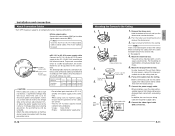
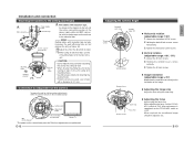
... the Camera Temporarily used , use the 2 mounting holes to fix the box to the ceiling or wall, fix the unit using the focus ring. R B SPOT RESET CORRECTION Setting switch Adjustment button L H IRIS LEVEL IRIS LEVEL Volume FOR SERVICE MONITOR 75Ω termination disconnected Monitor TV * The power to the Ceiling (Continued) 9. E-12 Adjusting the Camera Angle Tilt lock screws Horizontal Lock screw Variable range 120˚ L LEVEIRLIS H MONITOR SERFVOIRCE CORRECSTPIOOTN RESET PHASE R AUTO...
... the Camera Temporarily used , use the 2 mounting holes to fix the box to the ceiling or wall, fix the unit using the focus ring. R B SPOT RESET CORRECTION Setting switch Adjustment button L H IRIS LEVEL IRIS LEVEL Volume FOR SERVICE MONITOR 75Ω termination disconnected Monitor TV * The power to the Ceiling (Continued) 9. E-12 Adjusting the Camera Angle Tilt lock screws Horizontal Lock screw Variable range 120˚ L LEVEIRLIS H MONITOR SERFVOIRCE CORRECSTPIOOTN RESET PHASE R AUTO...
Instruction Manual
Page 9
... RESET CORRECTION Usage 1. E-14 E-15 English Installation and connection Adjusting the Camera Angle (Continued) Ⅲ Attach the dome cover. Remove the dome cover. • Switch on the camera and dome cover (I, II and III). FOCUS ADJ. Memo: • The white-spot correction feature of white-spot correction is maintained until the next correction is equipped with a white-spot correction feature. OFF OFF OFF AUTO LL...
... RESET CORRECTION Usage 1. E-14 E-15 English Installation and connection Adjusting the Camera Angle (Continued) Ⅲ Attach the dome cover. Remove the dome cover. • Switch on the camera and dome cover (I, II and III). FOCUS ADJ. Memo: • The white-spot correction feature of white-spot correction is maintained until the next correction is equipped with a white-spot correction feature. OFF OFF OFF AUTO LL...


