Instruction Manual
Page 1
...176; φ4-3/32 (103.5) • Design and specifications are subject to 6 mm (variable) Max. Model No. Others SPECIFICATIONS Ⅲ CAMERA Signal system: U type based on NTSC standard E type based on the body. TK-C205 Serial No. Retain this information for future reference....picture elements: U type 380,000 pixels, 768 (H) × 494 (V) E type 440,000 pixels, 752 (H) × 582 (V) Sync system: Line lock/Internal Video S/N: 50 dB (AGC OFF, Typ.) Horizontal resolution: 535 TV lines (Typ.) Minimum illumination: 4.8 l× (F1.2, AGC ON, 50%, WIDE end) (Typ.)...
...176; φ4-3/32 (103.5) • Design and specifications are subject to 6 mm (variable) Max. Model No. Others SPECIFICATIONS Ⅲ CAMERA Signal system: U type based on NTSC standard E type based on the body. TK-C205 Serial No. Retain this information for future reference....picture elements: U type 380,000 pixels, 768 (H) × 494 (V) E type 440,000 pixels, 752 (H) × 582 (V) Sync system: Line lock/Internal Video S/N: 50 dB (AGC OFF, Typ.) Horizontal resolution: 535 TV lines (Typ.) Minimum illumination: 4.8 l× (F1.2, AGC ON, 50%, WIDE end) (Typ.)...
Instruction Manual
Page 4
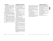
... to fall from the actual colors due to the operational principles of video taken under a fluorescent lamp should conform to not observing the installation instructions correctly. Please be ATW (Auto White). ● When this camera is not strong enough, make sure to apply reinforcement to the ceiling...using a lens wiper cloth (or a tissue). If it becoming impossible to record due to a problem in the video camera, VCR or video tape. Ⅲ We do not accept liability for indoor use the camera in the following places. • In a place exposed to rain or moisture. • In a place ...
... to fall from the actual colors due to the operational principles of video taken under a fluorescent lamp should conform to not observing the installation instructions correctly. Please be ATW (Auto White). ● When this camera is not strong enough, make sure to apply reinforcement to the ceiling...using a lens wiper cloth (or a tissue). If it becoming impossible to record due to a problem in the video camera, VCR or video tape. Ⅲ We do not accept liability for indoor use the camera in the following places. • In a place exposed to rain or moisture. • In a place ...
Instruction Manual
Page 5
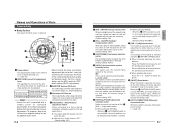
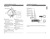
... the 8 [AUTO/MANU] switch is set for the camera. R B 10 11 SPOT RESET 12 CORRECTION 13 1 Camera Head For adjusting the angle of the camera, such as standard specification, the video may appear darker than the video during iris-level adjustment. To improve, adjust the iris ...Default setting: AUTO) 9 [INT/LL] Synchronization system selection switch This switch sets the synchronizing system for internal synchronization LL (Line Lock): The camera's vertical synchronization is pressed, white spots are corrected. ( ੬ page 15) E-7 English ON/OFF] Auto-gain control switch When the...
... the 8 [AUTO/MANU] switch is set for the camera. R B 10 11 SPOT RESET 12 CORRECTION 13 1 Camera Head For adjusting the angle of the camera, such as standard specification, the video may appear darker than the video during iris-level adjustment. To improve, adjust the iris ...Default setting: AUTO) 9 [INT/LL] Synchronization system selection switch This switch sets the synchronizing system for internal synchronization LL (Line Lock): The camera's vertical synchronization is pressed, white spots are corrected. ( ੬ page 15) E-7 English ON/OFF] Auto-gain control switch When the...
Instruction Manual
Page 6
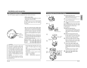
... drop prevention wire. E-8 Installation and connection System diagram Camera 1 Video signal Power Camera 2 Video signal Power Camera 3 Video signal Power Camera 4 Video signal Power Time Lapse VCR REC STOP/EJECT REC CHECK PAUSE/ REVERSE STILL PLAY REW FF VIDEO CASSETTE RECORDER COUNT/ CLOCK MENU SHIFT/TRACKING RESET /CANCEL.../PL RESET SR-L910E OPERATE OPE. Connect this to the ceiling slab or channel. LOCK VIDEO IN MONITOR Power Unit DC 12 V or AC 24 V TO CAMERA POWER TO CAMERA RX+ RX- VIDEO OUT SEE INSTRUCTION MANUAL 7 6 1 Power input cable To input DC 12 V or...
... drop prevention wire. E-8 Installation and connection System diagram Camera 1 Video signal Power Camera 2 Video signal Power Camera 3 Video signal Power Camera 4 Video signal Power Time Lapse VCR REC STOP/EJECT REC CHECK PAUSE/ REVERSE STILL PLAY REW FF VIDEO CASSETTE RECORDER COUNT/ CLOCK MENU SHIFT/TRACKING RESET /CANCEL.../PL RESET SR-L910E OPERATE OPE. Connect this to the ceiling slab or channel. LOCK VIDEO IN MONITOR Power Unit DC 12 V or AC 24 V TO CAMERA POWER TO CAMERA RX+ RX- VIDEO OUT SEE INSTRUCTION MANUAL 7 6 1 Power input cable To input DC 12 V or...
Instruction Manual
Page 7
... with surrounding parts. Installation and connection About Connection Cables • Turn OFF the power supply to all components before making connections. Ⅲ Video signal cables Connect the coaxial cables (BNC) to the DC 12V/AC 24V terminals on the camera side. (੬ See page 8) 4. Note Use the 3C-2V or 5C-2V...
... with surrounding parts. Installation and connection About Connection Cables • Turn OFF the power supply to all components before making connections. Ⅲ Video signal cables Connect the coaxial cables (BNC) to the DC 12V/AC 24V terminals on the camera side. (੬ See page 8) 4. Note Use the 3C-2V or 5C-2V...


