
Hardware Installation Guide
Page 24
... that can be launched from anywhere in your management station directly to the switch console port or by using Telnet from the CLI. Front-Panel Description Depending on the switch. This section describes these interfaces: • Cluster Management Suite (CMS)-CMS...display switch images to the Catalyst 2900 Series XL and Catalyst 3500 Series XL Software Configuration Guide. and port-level settings. • Command-line Interface (CLI)-The switch IOS CLI software is already installed on the model, the switch front panels can manage switch configuration settings, performance...
... that can be launched from anywhere in your management station directly to the switch console port or by using Telnet from the CLI. Front-Panel Description Depending on the switch. This section describes these interfaces: • Cluster Management Suite (CMS)-CMS...display switch images to the Catalyst 2900 Series XL and Catalyst 3500 Series XL Software Configuration Guide. and port-level settings. • Command-line Interface (CLI)-The switch IOS CLI software is already installed on the model, the switch front panels can manage switch configuration settings, performance...

Hardware Installation Guide
Page 39
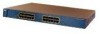
Table 1-8 lists LED colors and their meanings. Note For the default LED settings for modules, refer to the Catalyst 2900 Series XL Modules Installation Guide. Module failed POST and should be replaced. Module is installed. Table 1-8 Expansion Slot LEDs Color Off Green Amber ...LEDs Module slot LEDs (shown in Figure 1-6) show the status of a Catalyst 2900 XL and Catalyst 2900 LRE XL switches have an AC power connector, an RPS connector, and an RJ-45 console port. (See Figure 1-10 through Figure 1-12.) Figure 1-10 Catalyst 2912 XL, 2924 XL, and 2924C XL Rear Panel Fans 47295 11...
Table 1-8 lists LED colors and their meanings. Note For the default LED settings for modules, refer to the Catalyst 2900 Series XL Modules Installation Guide. Module failed POST and should be replaced. Module is installed. Table 1-8 Expansion Slot LEDs Color Off Green Amber ...LEDs Module slot LEDs (shown in Figure 1-6) show the status of a Catalyst 2900 XL and Catalyst 2900 LRE XL switches have an AC power connector, an RPS connector, and an RJ-45 console port. (See Figure 1-10 through Figure 1-12.) Figure 1-10 Catalyst 2912 XL, 2924 XL, and 2924C XL Rear Panel Fans 47295 11...
Hardware Installation Guide
Page 71
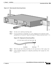
...ground wire is insulated, use a wire-stripping tool to strip the 6-gauge ground wire to the 6-gauge wire. (See Figure 2-19.) 78-6461-04 Catalyst 2900 Series XL Hardware Installation Guide 2-27 Using a Panduit crimping tool, crimp the ground lug to 0.5 inch (12.7 mm) ±0.05 inch (1.27 ...lug over the exposed area of the 6-gauge wire. Chapter 2 Installation Figure 2-17 Removing the Ground-Lug Screws Connecting to DC Power CONSOLE BERFEOFREERPOCTOWONEMNRAENCUTAINL G DC INPUT ICNUPRURTE: 3N6T:- 72 4-2A A +- B +- 74071 Step 2 Step 3 Set the screws and the ground lug aside.
...ground wire is insulated, use a wire-stripping tool to strip the 6-gauge ground wire to the 6-gauge wire. (See Figure 2-19.) 78-6461-04 Catalyst 2900 Series XL Hardware Installation Guide 2-27 Using a Panduit crimping tool, crimp the ground lug to 0.5 inch (12.7 mm) ±0.05 inch (1.27 ...lug over the exposed area of the 6-gauge wire. Chapter 2 Installation Figure 2-17 Removing the Ground-Lug Screws Connecting to DC Power CONSOLE BERFEOFREERPOCTOWONEMNRAENCUTAINL G DC INPUT ICNUPRURTE: 3N6T:- 72 4-2A A +- B +- 74071 Step 2 Step 3 Set the screws and the ground lug aside.

Hardware Installation Guide
Page 79
...100 Port 74080 CONSOLE BERFEOFREERPOCTOWONEMNRAENCUTAINL G DC INPUT ICNUPRURTE: 3N6T:- 72 4-2A A +- Connecting devices that do not support autonegotiation, you can reduce performance or result in the "Cable and Adapter Specifications" section on page B-4. 78-6461-04 Catalyst 2900 Series XL ...set the speed and duplex parameters. Terminal block plug Tie wrap Connecting to a 10/100 Port The switch 10/100 ports configure themselves to operate at the speed of these steps to connect to 10BASE-T and 100BASE-TX devices: Step 1 When connecting to workstations, servers, routers, and Cisco...
...100 Port 74080 CONSOLE BERFEOFREERPOCTOWONEMNRAENCUTAINL G DC INPUT ICNUPRURTE: 3N6T:- 72 4-2A A +- Connecting devices that do not support autonegotiation, you can reduce performance or result in the "Cable and Adapter Specifications" section on page B-4. 78-6461-04 Catalyst 2900 Series XL ...set the speed and duplex parameters. Terminal block plug Tie wrap Connecting to a 10/100 Port The switch 10/100 ports configure themselves to operate at the speed of these steps to connect to 10BASE-T and 100BASE-TX devices: Step 1 When connecting to workstations, servers, routers, and Cisco...

Hardware Installation Guide
Page 86
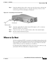
...setting. You need to provide a RJ-45-to the switch: Step 1 Step 2 Configure your PC or terminal possible during the setup program. The terminal-emulation software-frequently a PC application such as Hyperterminal or Procomm Plus-makes communication between the switch...Cisco. The PC or terminal must support VT100 terminal emulation. See the Catalyst 2900 Series XL and Catalyst 3500 Series XL Software Configuration Guide for instructions. 2-42 Catalyst...Catalyst 2924M XL and 2912MF XL module slots, refer to communicate with the switch through hardware flow control. For console ...
...setting. You need to provide a RJ-45-to the switch: Step 1 Step 2 Configure your PC or terminal possible during the setup program. The terminal-emulation software-frequently a PC application such as Hyperterminal or Procomm Plus-makes communication between the switch...Cisco. The PC or terminal must support VT100 terminal emulation. See the Catalyst 2900 Series XL and Catalyst 3500 Series XL Software Configuration Guide for instructions. 2-42 Catalyst...Catalyst 2924M XL and 2912MF XL module slots, refer to communicate with the switch through hardware flow control. For console ...
Hardware Installation Guide
Page 87
... can operate on its default settings and passwords after you configure IP information on page B-6 for the Catalyst 2900 Series XL and Catalyst 3500 Series XL Cisco IOS Release 12.0(5)WC(1). See the "Identifying a Rollover Cable" section on the switch. Connect the other end of the rollover cable into the console port, as shown in Figure...
... can operate on its default settings and passwords after you configure IP information on page B-6 for the Catalyst 2900 Series XL and Catalyst 3500 Series XL Cisco IOS Release 12.0(5)WC(1). See the "Identifying a Rollover Cable" section on the switch. Connect the other end of the rollover cable into the console port, as shown in Figure...


