
Hardware Installation Guide
Page 6
... Power Connectors 1-21 Internal Power Supply Connector 1-21 DC Power Connector 1-21 Cisco RPS Connector 1-22 Console Port 1-23 2 C H A P T E R Installation 2-1 Preparing for Installation 2-1 Warnings 2-1 EMC Regulatory Statements 2-4 U.S.A. 2-4 Taiwan 2-4 Japan 2-5 Korea 2-5 Hungary 2-6 Installation Guidelines 2-6 Verifying Package Contents 2-7 Installing the Switch on a Table or Shelf 2-9 Installing the Switch in a Rack 2-9 Removing Screws from the Switch 2-11 Attaching the Brackets to a Catalyst...
... Power Connectors 1-21 Internal Power Supply Connector 1-21 DC Power Connector 1-21 Cisco RPS Connector 1-22 Console Port 1-23 2 C H A P T E R Installation 2-1 Preparing for Installation 2-1 Warnings 2-1 EMC Regulatory Statements 2-4 U.S.A. 2-4 Taiwan 2-4 Japan 2-5 Korea 2-5 Hungary 2-6 Installation Guidelines 2-6 Verifying Package Contents 2-7 Installing the Switch on a Table or Shelf 2-9 Installing the Switch in a Rack 2-9 Removing Screws from the Switch 2-11 Attaching the Brackets to a Catalyst...

Hardware Installation Guide
Page 8
... Identifying a Rollover Cable B-6 Connecting to a PC B-6 Connecting to a Terminal B-7 Translated Safety Warnings C-1 Attaching the Cisco RPS (model PWR600-AC-RPS) C-1 Attaching the Cisco RPS (model PWR300-AC-RPS-N1) C-2 Qualified Personnel Warning C-3 Installation Warning C-4 Jewelry Removal Warning C-5 Stacking the... C-9 TN Power Warning C-10 Ground Connection Warning C-11 Circuit Breaker (15A) Warning C-12 Grounded Equipment Warning C-14 Supply Circuit Warning C-15 Voltage Warning C-16 Power Supply Warning C-17 Lightning Activity Warning C-19 Product Disposal Warning C-21 Catalyst 2900 Series ...
... Identifying a Rollover Cable B-6 Connecting to a PC B-6 Connecting to a Terminal B-7 Translated Safety Warnings C-1 Attaching the Cisco RPS (model PWR600-AC-RPS) C-1 Attaching the Cisco RPS (model PWR300-AC-RPS-N1) C-2 Qualified Personnel Warning C-3 Installation Warning C-4 Jewelry Removal Warning C-5 Stacking the... C-9 TN Power Warning C-10 Ground Connection Warning C-11 Circuit Breaker (15A) Warning C-12 Grounded Equipment Warning C-14 Supply Circuit Warning C-15 Voltage Warning C-16 Power Supply Warning C-17 Lightning Activity Warning C-19 Product Disposal Warning C-21 Catalyst 2900 Series ...

Hardware Installation Guide
Page 33
... in standby mode. If the switch power supply fails, the switch powers down and after 15 seconds restarts, using power from the RPS. The RPS and the switch AC power supply are both powered up power, if required. Chapter 1 Product Overview Front-Panel Description RPS LED The Catalyst 2912 LRE XL and Catalyst 2924 LRE XL switches use the Cisco RPS 600 (model PWR600-AC...
... in standby mode. If the switch power supply fails, the switch powers down and after 15 seconds restarts, using power from the RPS. The RPS and the switch AC power supply are both powered up power, if required. Chapter 1 Product Overview Front-Panel Description RPS LED The Catalyst 2912 LRE XL and Catalyst 2924 LRE XL switches use the Cisco RPS 600 (model PWR600-AC...

Hardware Installation Guide
Page 34
...Cisco Systems. The internal power supply in a switch has failed, and the RPS is the default mode. The port modes (Table 1-4 and Table 1-5) determine the type of the port LED colors also changes. When you change a mode, press the Mode button until the desired mode is in standby mode or in use by the switch... The port status. This is providing power to the switch (redundancy has been allocated to this device). Front-Panel Description Chapter 1 Product Overview Table 1-3 RPS LED on the Catalyst 2912 LRE XL and 2924 LRE XL Switches (continued) Color Solid amber Blinking amber...
...Cisco Systems. The internal power supply in a switch has failed, and the RPS is the default mode. The port modes (Table 1-4 and Table 1-5) determine the type of the port LED colors also changes. When you change a mode, press the Mode button until the desired mode is in standby mode or in use by the switch... The port status. This is providing power to the switch (redundancy has been allocated to this device). Front-Panel Description Chapter 1 Product Overview Table 1-3 RPS LED on the Catalyst 2912 LRE XL and 2924 LRE XL Switches (continued) Color Solid amber Blinking amber...
Hardware Installation Guide
Page 41
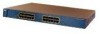
... 1-21 Note The Cisco RPS does not support the Catalyst 2924M XL DC switch. If you plan to use the internal power supply, use the supplied AC power cord to connect the AC power connector to the switch either through the internal power supply or through the Cisco RPS. Chapter 1 Product Overview Figure 1-13 Catalyst 2924M XL Rear Panel Power Connectors 74070 CONSOLE BERFEOFREERPOCTOWONEMNRAENCUTAINL...
... 1-21 Note The Cisco RPS does not support the Catalyst 2924M XL DC switch. If you plan to use the internal power supply, use the supplied AC power cord to connect the AC power connector to the switch either through the internal power supply or through the Cisco RPS. Chapter 1 Product Overview Figure 1-13 Catalyst 2924M XL Rear Panel Power Connectors 74070 CONSOLE BERFEOFREERPOCTOWONEMNRAENCUTAINL...

Hardware Installation Guide
Page 42
... PWR300-AC-RPS-N1)-supports the Catalyst 2912 LRE XL and 2924 LRE XL switches Note The Cisco RPS does not support the Catalyst 2924M XL DC switch. Power Connectors Chapter 1 Product Overview Caution You must connect the Catalyst 2924M XL DC switch only to a DC-input power source that use up to the ...RPS documentation. If the supply voltage is fully redundant, but the DC output to 150W DC each. RPS Connector on the Catalyst 2912 XL, 2924C XL, 2924 XL, 2924MF XL, and 2924M XL Switches The Cisco RPS 600 (model PWR600-AC-RPS) provides a quasi-redundant power source for each cable end...
... PWR300-AC-RPS-N1)-supports the Catalyst 2912 LRE XL and 2924 LRE XL switches Note The Cisco RPS does not support the Catalyst 2924M XL DC switch. Power Connectors Chapter 1 Product Overview Caution You must connect the Catalyst 2924M XL DC switch only to a DC-input power source that use up to the ...RPS documentation. If the supply voltage is fully redundant, but the DC output to 150W DC each. RPS Connector on the Catalyst 2912 XL, 2924C XL, 2924 XL, 2924MF XL, and 2924M XL Switches The Cisco RPS 600 (model PWR600-AC-RPS) provides a quasi-redundant power source for each cable end...

Hardware Installation Guide
Page 43
... Overview Power Connectors RPS Connector on the Catalyst 2912 LRE and 2924 LRE XL Switches The RPS is a 300W redundant power system that adapter from Cisco. Warning Attach only the Cisco RPS (model PWR300-AC-RPS-N1) to a terminal. Console Port You can connect a switch to prevent loss of network traffic. It automatically senses when the power supply of...
... Overview Power Connectors RPS Connector on the Catalyst 2912 LRE and 2924 LRE XL Switches The RPS is a 300W redundant power system that adapter from Cisco. Warning Attach only the Cisco RPS (model PWR300-AC-RPS-N1) to a terminal. Console Port You can connect a switch to prevent loss of network traffic. It automatically senses when the power supply of...
Hardware Installation Guide
Page 47
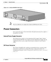
.... For systems with a power switch, line voltages are present within the power supply even when the power switch is off and the power cord is connected. Warning Do not work on the phase conductors (all national laws and regulations. 78-6461-04 Catalyst 2900 Series XL Hardware Installation...connect the chassis to earth ground during periods of this product should be grounded. For systems without a power switch, line voltages are present within the power supply when the power cord is connected. Warning A voltage mismatch can cause equipment damage and may pose a fire hazard....
.... For systems with a power switch, line voltages are present within the power supply even when the power switch is off and the power cord is connected. Warning Do not work on the phase conductors (all national laws and regulations. 78-6461-04 Catalyst 2900 Series XL Hardware Installation...connect the chassis to earth ground during periods of this product should be grounded. For systems without a power switch, line voltages are present within the power supply when the power cord is connected. Warning A voltage mismatch can cause equipment damage and may pose a fire hazard....
Hardware Installation Guide
Page 53
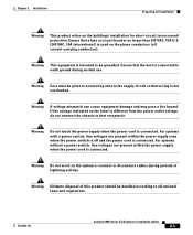
...devices, install the stabilizers before mounting or servicing the unit in the rack. Note Figure 2-1 shows brackets for one-rack-unit switches. 78-6461-04 Catalyst 2900 Series XL Hardware Installation Guide 2-9 Attach the four rubber feet to use. Figure 2-1 shows which mounting holes to the ...8226; When mounting this unit in "Powering On the Switch and Running POST" section on brackets for two-rack-unit modular switches. The supplied rack-mounting brackets can be mounted at the bottom of the unit. Place the switch on the table or shelf, power the switch as described in a rack, you ...
...devices, install the stabilizers before mounting or servicing the unit in the rack. Note Figure 2-1 shows brackets for one-rack-unit switches. 78-6461-04 Catalyst 2900 Series XL Hardware Installation Guide 2-9 Attach the four rubber feet to use. Figure 2-1 shows which mounting holes to the ...8226; When mounting this unit in "Powering On the Switch and Running POST" section on brackets for two-rack-unit modular switches. The supplied rack-mounting brackets can be mounted at the bottom of the unit. Place the switch on the table or shelf, power the switch as described in a rack, you ...
Hardware Installation Guide
Page 63
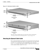
...78-6461-04 Catalyst 2900 Series XL Hardware Installation Guide 2-19 If the switch is mounted in the rack, power the switch as shown in Figure 2-12 to attach the cable guide to prevent the cables from obscuring the front panel of the switch and the other devices installed in "Powering On the Switch and Running POST...12 MODE 1X 2X 3X Catalyst 2900 SERIES XL 4X 5X 6X 7X 8X 9X 100BaseFX 10X 11X 12X 13X 14X 15X 16X 17X 18X 19X 20X 21X 22X 23X 24X Phillips machine screws After the switch is in a 19-, 23-, or 24-inch rack, use the supplied black screw as described ...
...78-6461-04 Catalyst 2900 Series XL Hardware Installation Guide 2-19 If the switch is mounted in the rack, power the switch as shown in Figure 2-12 to attach the cable guide to prevent the cables from obscuring the front panel of the switch and the other devices installed in "Powering On the Switch and Running POST...12 MODE 1X 2X 3X Catalyst 2900 SERIES XL 4X 5X 6X 7X 8X 9X 100BaseFX 10X 11X 12X 13X 14X 15X 16X 17X 18X 19X 20X 21X 22X 23X 24X Phillips machine screws After the switch is in a 19-, 23-, or 24-inch rack, use the supplied black screw as described ...
Hardware Installation Guide
Page 68
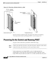
Catalyst 2900 Series XL Hardware Installation Guide 78-6461-04 SERIES 16x 17x 18x 19x 20x 21x 22x 23x 24x Powering On the Switch and Running POST Figure 2-16 Mounting a Modular Switch to ensure that run automatically to a Wall Vertical wall stud User-supplied screws User-supplied screws...47306 Vertical wall-mount Parallel wall-mount After the switch is mounted on the wall, power the switch as described in "Powering On the Switch and Running POST" section on the switch. Powering On the Switch and Running POST To power on the switch after you install it begins POST, a series...
Catalyst 2900 Series XL Hardware Installation Guide 78-6461-04 SERIES 16x 17x 18x 19x 20x 21x 22x 23x 24x Powering On the Switch and Running POST Figure 2-16 Mounting a Modular Switch to ensure that run automatically to a Wall Vertical wall stud User-supplied screws User-supplied screws...47306 Vertical wall-mount Parallel wall-mount After the switch is mounted on the wall, power the switch as described in "Powering On the Switch and Running POST" section on the switch. Powering On the Switch and Running POST To power on the switch after you install it begins POST, a series...
Hardware Installation Guide
Page 159
... (telco rack-mount) modules 1-8 mounting brackets 2-9 attaching 2-11, 2-15, 2-22 N no on/off switch warning C-24 O overtemperature warning C-9 P PC, connecting to switch 2-42 performance problems, solving 3-3 personnel warning C-3 pinouts 10/100BASE-T ports B-2 cable, straight-through and crossover...16 to 1-18 POST results 2-24 power connecting to 2-24 warning C-15 power connectors 1-21 power on 2-24 power supply AC power outlet 1-21 RPS connector 1-21 warning C-17 product disposal warning C-21 Q qualified personnel warning C-3 78-6461-04 Catalyst 2900 Series XL Hardware Installation Guide ...
... (telco rack-mount) modules 1-8 mounting brackets 2-9 attaching 2-11, 2-15, 2-22 N no on/off switch warning C-24 O overtemperature warning C-9 P PC, connecting to switch 2-42 performance problems, solving 3-3 personnel warning C-3 pinouts 10/100BASE-T ports B-2 cable, straight-through and crossover...16 to 1-18 POST results 2-24 power connecting to 2-24 warning C-15 power connectors 1-21 power on 2-24 power supply AC power outlet 1-21 RPS connector 1-21 warning C-17 product disposal warning C-21 Q qualified personnel warning C-3 78-6461-04 Catalyst 2900 Series XL Hardware Installation Guide ...
Hardware Installation Guide
Page 160
... cables straight-through B-4 SunNet Manager 1-4 supply circuit warning C-15 switch powering on 2-24 switched ports, module 1-8 System LED 1-12 T telco racks 2-15 telephone network power warning See TN power warning C-10 temperature maximum for installation 2-7, A-2 warning C-9 temperature warning C-9 terminal, connecting to switch 2-42 terminal adapter pinouts RH-45-to-RJ-45 B-7 IN-6 Catalyst 2900 Series XL Hardware Installation...
... cables straight-through B-4 SunNet Manager 1-4 supply circuit warning C-15 switch powering on 2-24 switched ports, module 1-8 System LED 1-12 T telco racks 2-15 telephone network power warning See TN power warning C-10 temperature maximum for installation 2-7, A-2 warning C-9 temperature warning C-9 terminal, connecting to switch 2-42 terminal adapter pinouts RH-45-to-RJ-45 B-7 IN-6 Catalyst 2900 Series XL Hardware Installation...

