
Hardware Installation Guide
Page 24
... platforms such as HP OpenView or SunNet Manager. and port-level settings. • Command-line Interface (CLI)-The switch IOS CLI software is enhanced to modify switch- You can manage switch configuration settings, performance, security, and collect statistics by using SNMP management applications ...anywhere in your management station directly to the switch console port or by using Telnet from a remote management station. • Simple network management protocol (SNMP)-SNMP provides a means to the Catalyst 2900 Series XL and Catalyst 3500 Series XL Software Configuration Guide. Using...
... platforms such as HP OpenView or SunNet Manager. and port-level settings. • Command-line Interface (CLI)-The switch IOS CLI software is enhanced to modify switch- You can manage switch configuration settings, performance, security, and collect statistics by using SNMP management applications ...anywhere in your management station directly to the switch console port or by using Telnet from a remote management station. • Simple network management protocol (SNMP)-SNMP provides a means to the Catalyst 2900 Series XL and Catalyst 3500 Series XL Software Configuration Guide. Using...

Hardware Installation Guide
Page 39
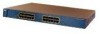
...(shown in Figure 1-6) show the status of a Catalyst 2900 XL and Catalyst 2900 LRE XL switches have an AC power connector, an RPS connector, and an RJ-45 console port. (See Figure 1-10 through Figure 1-12.) Figure 1-10 Catalyst 2912 XL, 2924 XL, and 2924C XL Rear ... power connector +5DVSCPIENPCPO@IUWF9TIAEES,[email protected] CONSOLE Redundant power system RJ-45 connector connector 78-6461-04 Catalyst 2900 Series XL Hardware Installation Guide 1-19 Note For the default LED settings for modules, refer to the Catalyst 2900 Series XL Modules Installation Guide. Table 1-8 ...
...(shown in Figure 1-6) show the status of a Catalyst 2900 XL and Catalyst 2900 LRE XL switches have an AC power connector, an RPS connector, and an RJ-45 console port. (See Figure 1-10 through Figure 1-12.) Figure 1-10 Catalyst 2912 XL, 2924 XL, and 2924C XL Rear ... power connector +5DVSCPIENPCPO@IUWF9TIAEES,[email protected] CONSOLE Redundant power system RJ-45 connector connector 78-6461-04 Catalyst 2900 Series XL Hardware Installation Guide 1-19 Note For the default LED settings for modules, refer to the Catalyst 2900 Series XL Modules Installation Guide. Table 1-8 ...
Hardware Installation Guide
Page 71
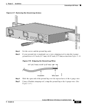
... Removing the Ground-Lug Screws Connecting to the 6-gauge wire. (See Figure 2-19.) 78-6461-04 Catalyst 2900 Series XL Hardware Installation Guide 2-27 Using a Panduit crimping tool, crimp the ground lug to DC Power CONSOLE BERFEOFREERPOCTOWONEMNRAENCUTAINL G DC INPUT ICNUPRURTE: 3N6T:- 72 4-2A A +- If your ground wire is insulated, use a wire-stripping...) 74076 Step 4 Step 5 Insulation Wire lead Slide the open end of the ground lug over the exposed area of the 6-gauge wire. B +- 74071 Step 2 Step 3 Set the screws and the ground lug aside.
... Removing the Ground-Lug Screws Connecting to the 6-gauge wire. (See Figure 2-19.) 78-6461-04 Catalyst 2900 Series XL Hardware Installation Guide 2-27 Using a Panduit crimping tool, crimp the ground lug to DC Power CONSOLE BERFEOFREERPOCTOWONEMNRAENCUTAINL G DC INPUT ICNUPRURTE: 3N6T:- 72 4-2A A +- If your ground wire is insulated, use a wire-stripping...) 74076 Step 4 Step 5 Insulation Wire lead Slide the open end of the ground lug over the exposed area of the 6-gauge wire. B +- 74071 Step 2 Step 3 Set the screws and the ground lug aside.

Hardware Installation Guide
Page 79
...Step 1 When connecting to workstations, servers, routers, and Cisco IP Phones, connect a straight-through Category 5 cable to operate at the speed of these methods for the cables are described in no linkage. When connecting to a 10/100 Port 74080 CONSOLE BERFEOFREERPOCTOWONEMNRAENCUTAINL G DC INPUT ICNUPRURTE: 3N6T:- 72 4-2A A... • Set the port speed and duplex parameters on both ends of the connection. Terminal block plug Tie wrap Connecting to a 10/100 Port The switch 10/100 ports configure themselves to an RJ-45 connector on page B-4. 78-6461-04 Catalyst 2900 Series ...
...Step 1 When connecting to workstations, servers, routers, and Cisco IP Phones, connect a straight-through Category 5 cable to operate at the speed of these methods for the cables are described in no linkage. When connecting to a 10/100 Port 74080 CONSOLE BERFEOFREERPOCTOWONEMNRAENCUTAINL G DC INPUT ICNUPRURTE: 3N6T:- 72 4-2A A... • Set the port speed and duplex parameters on both ends of the connection. Terminal block plug Tie wrap Connecting to a 10/100 Port The switch 10/100 ports configure themselves to an RJ-45 connector on page B-4. 78-6461-04 Catalyst 2900 Series ...

Hardware Installation Guide
Page 86
...terminal-emulation software to the switch console port. The terminal-emulation software-frequently a PC application such as Hyperterminal or Procomm Plus-makes communication between the switch and your PC- You can change the port baud rate to its original setting. Configure the baud rate ...parity After you have accessed the switch, you want to connect the switch console port to -DB-25 female DTE adapter if you can order a kit (part number ACS-DSBUASYN=) containing that adapter from Cisco. See the Catalyst 2900 Series XL and Catalyst 3500 Series XL Software Configuration Guide ...
...terminal-emulation software to the switch console port. The terminal-emulation software-frequently a PC application such as Hyperterminal or Procomm Plus-makes communication between the switch and your PC- You can change the port baud rate to its original setting. Configure the baud rate ...parity After you have accessed the switch, you want to connect the switch console port to -DB-25 female DTE adapter if you can order a kit (part number ACS-DSBUASYN=) containing that adapter from Cisco. See the Catalyst 2900 Series XL and Catalyst 3500 Series XL Software Configuration Guide ...
Hardware Installation Guide
Page 87
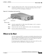
...DB-9 female DTE adapter to a PC, or attach an appropriate adapter to the Release Notes for a description of the rollover cable into the console port, as shown in Figure 2-31. Where to Go Next Step 3 Using the supplied rollover cable, connect one end of the pinout.... a Rollover Cable" section on the switch. Chapter 2 Installation Where to Go Next After the switch passes POST, it can operate on its default settings and passwords after you configure IP information on page B-6 for the Catalyst 2900 Series XL and Catalyst 3500 Series XL Cisco IOS Release 12.0(5)WC(1). Start the ...
...DB-9 female DTE adapter to a PC, or attach an appropriate adapter to the Release Notes for a description of the rollover cable into the console port, as shown in Figure 2-31. Where to Go Next Step 3 Using the supplied rollover cable, connect one end of the pinout.... a Rollover Cable" section on the switch. Chapter 2 Installation Where to Go Next After the switch passes POST, it can operate on its default settings and passwords after you configure IP information on page B-6 for the Catalyst 2900 Series XL and Catalyst 3500 Series XL Cisco IOS Release 12.0(5)WC(1). Start the ...


