
Hardware Installation Guide
Page 6
... DC Power Connector 1-21 Cisco RPS Connector 1-22 Console Port 1-23 2 C H A P T E R Installation 2-1 Preparing for Installation 2-1 Warnings 2-1 EMC Regulatory Statements 2-4 U.S.A. 2-4 Taiwan 2-4 Japan 2-5 Korea 2-5 Hungary 2-6 Installation Guidelines 2-6 Verifying Package Contents 2-7 Installing the Switch on a Table or Shelf 2-9 Installing the Switch in a Rack 2-9 Removing Screws from the Switch 2-11 Attaching the Brackets to a Catalyst 2912 XL, 2924C XL...
... DC Power Connector 1-21 Cisco RPS Connector 1-22 Console Port 1-23 2 C H A P T E R Installation 2-1 Preparing for Installation 2-1 Warnings 2-1 EMC Regulatory Statements 2-4 U.S.A. 2-4 Taiwan 2-4 Japan 2-5 Korea 2-5 Hungary 2-6 Installation Guidelines 2-6 Verifying Package Contents 2-7 Installing the Switch on a Table or Shelf 2-9 Installing the Switch in a Rack 2-9 Removing Screws from the Switch 2-11 Attaching the Brackets to a Catalyst 2912 XL, 2924C XL...

Hardware Installation Guide
Page 7
...18 Attaching the Optional Cable Guide 2-19 Installing the Switch on a Wall 2-20 Attaching the Brackets to the Switch 2-21 Mounting the Switch to a Wall 2-22 Powering On the Switch and Running POST 2-24 Connecting to DC Power 2-25 Preparing for Installation 2-25 Grounding the Switch 2-26 Wiring the DC-Input Power Source 2-29... Correcting Module POST Failures 3-2 Diagnosing Problems 3-3 Technical Specifications A-1 Connectors and Cable Specifications B-1 Connector Specifications B-1 10/100 Ports B-1 100BASE-FX Ports B-2 Contents 78-6461-04 Catalyst 2900 Series XL Hardware Installation Guide vii
...18 Attaching the Optional Cable Guide 2-19 Installing the Switch on a Wall 2-20 Attaching the Brackets to the Switch 2-21 Mounting the Switch to a Wall 2-22 Powering On the Switch and Running POST 2-24 Connecting to DC Power 2-25 Preparing for Installation 2-25 Grounding the Switch 2-26 Wiring the DC-Input Power Source 2-29... Correcting Module POST Failures 3-2 Diagnosing Problems 3-3 Technical Specifications A-1 Connectors and Cable Specifications B-1 Connector Specifications B-1 10/100 Ports B-1 100BASE-FX Ports B-2 Contents 78-6461-04 Catalyst 2900 Series XL Hardware Installation Guide vii

Hardware Installation Guide
Page 9
INDEX Class 1 Laser Product Warning C-22 Laser Beam Exposure Warning C-23 No On/Off Switch Warning C-24 Chassis Warning-Rack-Mounting and Servicing C-25 Reinforced Insulation Warning C-29 LAN Connections Only Warning C-30 No Field-Replaceable Units Warning C-31 Installation ... Equipment Warning C-36 Ground Connection Warning C-37 Qualified Personnel Warning C-38 DC Power Disconnection Warning C-39 Exposed Wire Lead Warning C-41 Contents 78-6461-04 Catalyst 2900 Series XL Hardware Installation Guide ix
INDEX Class 1 Laser Product Warning C-22 Laser Beam Exposure Warning C-23 No On/Off Switch Warning C-24 Chassis Warning-Rack-Mounting and Servicing C-25 Reinforced Insulation Warning C-29 LAN Connections Only Warning C-30 No Field-Replaceable Units Warning C-31 Installation ... Equipment Warning C-36 Ground Connection Warning C-37 Qualified Personnel Warning C-38 DC Power Disconnection Warning C-39 Exposed Wire Lead Warning C-41 Contents 78-6461-04 Catalyst 2900 Series XL Hardware Installation Guide ix

Hardware Installation Guide
Page 11
... 1, "Product Overview," summarizes the switch features and describes the ports, the standards they support, and the LEDs. Purpose The Catalyst 2900 Series XL Hardware Installation Guide documents the hardware features of the switches, explains how to identify and resolve..., or on a wall. Chapter 2, "Installation," provides the procedures for installing and configuring a Catalyst 2900 series XL switch. Chapter 3, "Troubleshooting," describes how to install a switch, and provides troubleshooting information and specifications. We assume that might arise when you are familiar with ...
... 1, "Product Overview," summarizes the switch features and describes the ports, the standards they support, and the LEDs. Purpose The Catalyst 2900 Series XL Hardware Installation Guide documents the hardware features of the switches, explains how to identify and resolve..., or on a wall. Chapter 2, "Installation," provides the procedures for installing and configuring a Catalyst 2900 series XL switch. Chapter 3, "Troubleshooting," describes how to install a switch, and provides troubleshooting information and specifications. We assume that might arise when you are familiar with ...

Hardware Installation Guide
Page 12
... adapters that could result in angle brackets (< >). Examples use these conventions: • Commands and keywords are in boldface. • Arguments for the switches and the regulatory agency approvals. Catalyst 2900 Series XL Hardware Installation Guide xii 78-6461-04 In this situation, you might do something that can be careful. Appendix C, "Translated...
... adapters that could result in angle brackets (< >). Examples use these conventions: • Commands and keywords are in boldface. • Arguments for the switches and the regulatory agency approvals. Catalyst 2900 Series XL Hardware Installation Guide xii 78-6461-04 In this situation, you might do something that can be careful. Appendix C, "Translated...

Hardware Installation Guide
Page 15
... xvi. • Release Notes for the Catalyst 2900 Series XL and Catalyst 3500 Series XL Switches (not orderable but is available on Cisco.com) Note Switch requirements and procedures for initial configurations and software upgrades tend to the release notes on Cisco.com for the latest information. 78-6461-04 Catalyst 2900 Series XL Hardware Installation Guide...
... xvi. • Release Notes for the Catalyst 2900 Series XL and Catalyst 3500 Series XL Switches (not orderable but is available on Cisco.com) Note Switch requirements and procedures for initial configurations and software upgrades tend to the release notes on Cisco.com for the latest information. 78-6461-04 Catalyst 2900 Series XL Hardware Installation Guide...

Hardware Installation Guide
Page 16
... online help (available only from the switch CMS software) • Catalyst 2900 Series XL Hardware Installation Guide (order number DOC-786461=) • Catalyst 3500 Series XL Hardware Installation Guide (order number DOC-786456=) • Catalyst 2900 Series XL Modules Installation Guide (order...1000BASE-T Gigabit Interface Converter Installation Note (not orderable but is available on Cisco.com) • Catalyst GigaStack Gigabit Interface Converter Hardware Installation Guide (order number DOC-786460=) • Cisco LRE CPE Hardware Installation Guide (order number DOC-7811469=) • ...
... online help (available only from the switch CMS software) • Catalyst 2900 Series XL Hardware Installation Guide (order number DOC-786461=) • Catalyst 3500 Series XL Hardware Installation Guide (order number DOC-786456=) • Catalyst 2900 Series XL Modules Installation Guide (order...1000BASE-T Gigabit Interface Converter Installation Note (not orderable but is available on Cisco.com) • Catalyst GigaStack Gigabit Interface Converter Hardware Installation Guide (order number DOC-786460=) • Cisco LRE CPE Hardware Installation Guide (order number DOC-7811469=) • ...

Hardware Installation Guide
Page 21
..., Cisco IP Phones, and other network devices such as backbone switches, aggregating 10/100 and Gigabit Ethernet traffic from other switches. The 2900 XL LRE switches employ Long-Reach Ethernet (LRE), a very-high-data-rate digital subscriber line (VDSL)-based technology that describe the Catalyst 2900 series XL switches, hereafter referred to as the switches. • Switch features...
..., Cisco IP Phones, and other network devices such as backbone switches, aggregating 10/100 and Gigabit Ethernet traffic from other switches. The 2900 XL LRE switches employ Long-Reach Ethernet (LRE), a very-high-data-rate digital subscriber line (VDSL)-based technology that describe the Catalyst 2900 series XL switches, hereafter referred to as the switches. • Switch features...

Hardware Installation Guide
Page 22
...converter • On the Catalyst 2912 LRE XL and 2924 LRE XL switches, up to 24 LRE ports through one RJ-21 connector and hot swapping capability with the Cisco LRE customer premises equipment (CPE) devices • Supports up to 2048 MAC addresses on the Catalyst 2924 XL, 2924C XL,... and 2912 XL switches • Supports up to 8192 MAC addresses on the Catalyst 2924M XL, Catalyst 2924M XL DC and Catalyst 2912MF XL switches Figure 1-1 shows ...
...converter • On the Catalyst 2912 LRE XL and 2924 LRE XL switches, up to 24 LRE ports through one RJ-21 connector and hot swapping capability with the Cisco LRE customer premises equipment (CPE) devices • Supports up to 2048 MAC addresses on the Catalyst 2924 XL, 2924C XL,... and 2912 XL switches • Supports up to 8192 MAC addresses on the Catalyst 2924M XL, Catalyst 2924M XL DC and Catalyst 2912MF XL switches Figure 1-1 shows ...

Hardware Installation Guide
Page 23
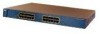
Chapter 1 Product Overview Figure 1-1 Catalyst 2900 Series XL Switches Version Number Description WS-C2912-LRE-XL 4 fixed autosensing 10/100 ports INPUT OUTPUT PWR PWR RESET TEMP FAN 9X 10X 11X 12X 12 LRE ports Cisco RPS 300 WS-C2924-LRE-XL 4 fixed autosensing 10/100 ports 24 LRE ports INPUT OUTPUT PWR PWR... 4 5 100BASE-FX 6 7 8 9 10 11 12 WS-C2924M-XL WS-C2924M-XLEM-DC 24 fixed autosensing 10/100 ports 2 expansion slots 12 MODE 1X 2X 3X Catalyst 2900 SERIES XL 4X 5X 6X 7X 8X 9X 10X 11X 100BaseFX 12X 13X 14X 15X 16X 17X 18X 19X 20X 21X 22X 23X 24X...
Chapter 1 Product Overview Figure 1-1 Catalyst 2900 Series XL Switches Version Number Description WS-C2912-LRE-XL 4 fixed autosensing 10/100 ports INPUT OUTPUT PWR PWR RESET TEMP FAN 9X 10X 11X 12X 12 LRE ports Cisco RPS 300 WS-C2924-LRE-XL 4 fixed autosensing 10/100 ports 24 LRE ports INPUT OUTPUT PWR PWR... 4 5 100BASE-FX 6 7 8 9 10 11 12 WS-C2924M-XL WS-C2924M-XLEM-DC 24 fixed autosensing 10/100 ports 2 expansion slots 12 MODE 1X 2X 3X Catalyst 2900 SERIES XL 4X 5X 6X 7X 8X 9X 10X 11X 100BaseFX 12X 13X 14X 15X 16X 17X 18X 19X 20X 21X 22X 23X 24X...

Hardware Installation Guide
Page 24
... CiscoWorks2000 LAN Management Suite (LMS) and HP OpenView. Using CMS, you can fully configure and monitor the switch and switch cluster members from the CLI. You can fully configure and monitor a standalone switch, a specific cluster member, or an entire switch cluster. Catalyst 2900 Series XL Hardware Installation Guide 1-4 78-6461-04 You can manage the...
... CiscoWorks2000 LAN Management Suite (LMS) and HP OpenView. Using CMS, you can fully configure and monitor the switch and switch cluster members from the CLI. You can fully configure and monitor a standalone switch, a specific cluster member, or an entire switch cluster. Catalyst 2900 Series XL Hardware Installation Guide 1-4 78-6461-04 You can manage the...

Hardware Installation Guide
Page 26
...for speed and duplex autonegotiation, compliant with IEEE 802.3U. Cisco IP Phones-connected to switches or hubs, use Category 3 and 4 cables. Catalyst 2900 Series XL Hardware Installation Guide 1-6 78-6461-04 When connecting the switch to 328 feet (100 meters) away: • 10BASE-T-compatible... any compatible network device up to workstations, servers, routers, and Cisco IP Phones, be explicitly set for Cisco IP Phones and per-port priority override. The 10/100 ports on the Catalyst 3524-PWR XL switch, refer to operate in Appendix B, "Connectors and Cable Specifications." ...
...for speed and duplex autonegotiation, compliant with IEEE 802.3U. Cisco IP Phones-connected to switches or hubs, use Category 3 and 4 cables. Catalyst 2900 Series XL Hardware Installation Guide 1-6 78-6461-04 When connecting the switch to 328 feet (100 meters) away: • 10BASE-T-compatible... any compatible network device up to workstations, servers, routers, and Cisco IP Phones, be explicitly set for Cisco IP Phones and per-port priority override. The 10/100 ports on the Catalyst 3524-PWR XL switch, refer to operate in Appendix B, "Connectors and Cable Specifications." ...

Hardware Installation Guide
Page 27
...port on the same Catalyst 2900 LRE XL switch, and you can hot swap the CPE devices without powering down the switch or disrupting the other telephone services are configured for each CPE device can be connected to the patch panel through a private branch exchange (PBX) switch, a Cisco LRE 48 POTS Splitter... can reach speeds of up to 15 Mbps (full duplex) and distances of up to 6562 feet (2 kilometers). You can connect Cisco 575 LRE CPE and Cisco 585 LRE CPE devices to LRE ports on the ...
...port on the same Catalyst 2900 LRE XL switch, and you can hot swap the CPE devices without powering down the switch or disrupting the other telephone services are configured for each CPE device can be connected to the patch panel through a private branch exchange (PBX) switch, a Cisco LRE 48 POTS Splitter... can reach speeds of up to 15 Mbps (full duplex) and distances of up to 6562 feet (2 kilometers). You can connect Cisco 575 LRE CPE and Cisco 585 LRE CPE devices to LRE ports on the ...

Hardware Installation Guide
Page 28
... to the Installation Notes for the Catalyst 2900 XL hot-swappable modules. For more information about the Cisco LRE 48 POTS Splitter (PS-1M-LRE-48), refer to the PSTN. Digital telephones connected to digital PBX switches that use the 0 to the ...Integrated Services Digital Network (ISDN), and digital private branch exchange (PBX) switch telephones that the module slots support. Due to 700 kHz frequency range. For more information about homologated POTS splitters, contact your Cisco sales representative. Front-Panel Description Chapter 1 Product Overview (PSTN). Table ...
... to the Installation Notes for the Catalyst 2900 XL hot-swappable modules. For more information about the Cisco LRE 48 POTS Splitter (PS-1M-LRE-48), refer to the PSTN. Digital telephones connected to digital PBX switches that use the 0 to the ...Integrated Services Digital Network (ISDN), and digital private branch exchange (PBX) switch telephones that the module slots support. Due to 700 kHz frequency range. For more information about homologated POTS splitters, contact your Cisco sales representative. Front-Panel Description Chapter 1 Product Overview (PSTN). Table ...

Hardware Installation Guide
Page 29
... information on self-test (POST) verifies that the module is reduced to the Release Notes for Catalyst 2900 series XL switches. Refer to select a port mode. If you insert them in a 2924M XL or Catalyst 2912MF XL switch (both supporting 8192 MAC addresses), the module fails POST. Figure 1-5, Figure 1-6, and Figure 1-7 show the location...
... information on self-test (POST) verifies that the module is reduced to the Release Notes for Catalyst 2900 series XL switches. Refer to select a port mode. If you insert them in a 2924M XL or Catalyst 2912MF XL switch (both supporting 8192 MAC addresses), the module fails POST. Figure 1-5, Figure 1-6, and Figure 1-7 show the location...

Hardware Installation Guide
Page 30
...LEDs 10/100 port LEDs System LED Port mode LEDs MODE 1X 2X 3X 4X 5X 6X 7X Mode RPS button LED 47288 1-10 Catalyst 2900 Series XL Hardware Installation Guide 78-6461-04 Front-Panel Description Chapter 1 Product Overview All of the LEDs described in this section except... the utilization meter (UTL) are visible on the Cluster Management Suite (CMS) window and, if the switch is a cluster member, on the CMS Cluster Manager window. The Catalyst 2900 Series XL and Catalyst 3500 Series XL Software Configuration Guide describes how to use CMS to manage standalone or individual...
...LEDs 10/100 port LEDs System LED Port mode LEDs MODE 1X 2X 3X 4X 5X 6X 7X Mode RPS button LED 47288 1-10 Catalyst 2900 Series XL Hardware Installation Guide 78-6461-04 Front-Panel Description Chapter 1 Product Overview All of the LEDs described in this section except... the utilization meter (UTL) are visible on the Cluster Management Suite (CMS) window and, if the switch is a cluster member, on the CMS Cluster Manager window. The Catalyst 2900 Series XL and Catalyst 3500 Series XL Software Configuration Guide describes how to use CMS to manage standalone or individual...

Hardware Installation Guide
Page 32
.... For information on the System LED colors during POST, see the "Powering On the Switch and Running POST" section on page 2-24. 1-12 Catalyst 2900 Series XL Hardware Installation Guide 78-6461-04 Front-Panel Description Figure 1-7 Catalyst 2912 LRE XL and 2924 LRE XL LEDs 10/100 port LEDs Chapter 1 Product Overview...
.... For information on the System LED colors during POST, see the "Powering On the Switch and Running POST" section on page 2-24. 1-12 Catalyst 2900 Series XL Hardware Installation Guide 78-6461-04 Front-Panel Description Figure 1-7 Catalyst 2912 LRE XL and 2924 LRE XL LEDs 10/100 port LEDs Chapter 1 Product Overview...

Hardware Installation Guide
Page 33
...Description RPS LED The Catalyst 2912 LRE XL and Catalyst 2924 LRE XL switches use the Cisco RPS 600 (model PWR600-AC-RPS). Refer to provide back-up . If the switch power supply fails, the switch powers down and after 15 seconds restarts, using power from the RPS. The switch goes through its normal... up power, if required. Note This is operational. For more information see the "Cisco RPS Connector" section on the Catalyst 2912 XL, 2924C XL, 2924 XL, 2924MF XL, 2924M XL, and 2924M XL DC Switches Color Off Green Blinking green Amber RPS Status RPS is connected and ready to the...
...Description RPS LED The Catalyst 2912 LRE XL and Catalyst 2924 LRE XL switches use the Cisco RPS 600 (model PWR600-AC-RPS). Refer to provide back-up . If the switch power supply fails, the switch powers down and after 15 seconds restarts, using power from the RPS. The switch goes through its normal... up power, if required. Note This is operational. For more information see the "Cisco RPS Connector" section on the Catalyst 2912 XL, 2924C XL, 2924 XL, 2924MF XL, 2924M XL, and 2924M XL DC Switches Color Off Green Blinking green Amber RPS Status RPS is connected and ready to the...

Hardware Installation Guide
Page 34
... is the default mode. The current bandwidth in a fault condition. Front-Panel Description Chapter 1 Product Overview Table 1-3 RPS LED on the Catalyst 2912 LRE XL and 2924 LRE XL Switches (continued) Color Solid amber Blinking amber RPS Status The RPS is in standby mode or in use by the... port operating speed: 10 or 100 Mbps. 1-14 Catalyst 2900 Series XL Hardware Installation Guide 78-6461-04 This is highlighted. If it does not, the RPS fan could have a port LED. Contact Cisco Systems. The internal power supply in a switch has failed, and the RPS is providing power to the...
... is the default mode. The current bandwidth in a fault condition. Front-Panel Description Chapter 1 Product Overview Table 1-3 RPS LED on the Catalyst 2912 LRE XL and 2924 LRE XL Switches (continued) Color Solid amber Blinking amber RPS Status The RPS is in standby mode or in use by the... port operating speed: 10 or 100 Mbps. 1-14 Catalyst 2900 Series XL Hardware Installation Guide 78-6461-04 This is highlighted. If it does not, the RPS fan could have a port LED. Contact Cisco Systems. The internal power supply in a switch has failed, and the RPS is providing power to the...

Hardware Installation Guide
Page 35
Note When the LRE mode is active, the 10/100 switch ports on all Catalyst 2900 XL and Catalyst 3500 XL switches except the Catalyst 2912 LRE XL and Catalyst 2924 LRE XL switches. Default mode on the Catalyst 2912 LRE XL and Catalyst 2924 LRE XL continue to show Ethernet link status. The port operating speed: ...10 or 100 Mbps. Ethernet link status of the LRE ports on the Catalyst 2912 LRE XL and Catalyst 2924 LRE XL switches. The default setting is half duplex. Default mode on the remote CPE. The default setting is auto. 78-6461-04...
Note When the LRE mode is active, the 10/100 switch ports on all Catalyst 2900 XL and Catalyst 3500 XL switches except the Catalyst 2912 LRE XL and Catalyst 2924 LRE XL switches. Default mode on the Catalyst 2912 LRE XL and Catalyst 2924 LRE XL continue to show Ethernet link status. The port operating speed: ...10 or 100 Mbps. Ethernet link status of the LRE ports on the Catalyst 2912 LRE XL and Catalyst 2924 LRE XL switches. The default setting is half duplex. Default mode on the remote CPE. The default setting is auto. 78-6461-04...


