
Hardware Installation Guide
Page 23
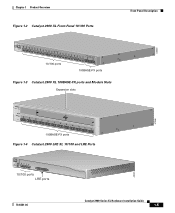
Chapter 1 Product Overview Figure 1-1 Catalyst 2900 Series XL Switches Version Number Description WS-C2912-LRE-XL 4 fixed autosensing 10/100 ports INPUT OUTPUT PWR PWR RESET TEMP FAN 9X 10X 11X 12X 12 LRE ports Cisco RPS 300 WS-C2924-LRE-XL 4 fixed autosensing 10/100 ports 24 LRE ports INPUT OUTPUT PWR PWR RESET... TEMP FAN 9X 10X 11X 12X Cisco RPS 300 WS-C2912-XL 12 fixed autosensing 10/100 ports MODE 1X 2X 3X 4X 5X 6X 7X 8X 9X 10X 10BaseT/100BASE-TX 11X 12X Catalyst 2900 SERIES XL WS-C2924C-XL 22 fixed autosensing...
Chapter 1 Product Overview Figure 1-1 Catalyst 2900 Series XL Switches Version Number Description WS-C2912-LRE-XL 4 fixed autosensing 10/100 ports INPUT OUTPUT PWR PWR RESET TEMP FAN 9X 10X 11X 12X 12 LRE ports Cisco RPS 300 WS-C2924-LRE-XL 4 fixed autosensing 10/100 ports 24 LRE ports INPUT OUTPUT PWR PWR RESET... TEMP FAN 9X 10X 11X 12X Cisco RPS 300 WS-C2912-XL 12 fixed autosensing 10/100 ports MODE 1X 2X 3X 4X 5X 6X 7X 8X 9X 10X 10BaseT/100BASE-TX 11X 12X Catalyst 2900 SERIES XL WS-C2924C-XL 22 fixed autosensing...
Hardware Installation Guide
Page 25
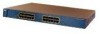
... XL 23 24 10/100 ports 100BASE-FX ports Figure 1-3 Catalyst 2900 XL 100BASE-FX ports and Module Slots Expansion slots 47286 12 1 MODE 2 3 Catalyst 2900 SERIES XL 4 5 100BASE-FX 6 7 8 9 10 11 12 100BASE-FX ports Figure 1-4 Catalyst 2900 LRE XL 10/100 and LRE Ports INPUT OUTPUT PWR... PWR RESET TEMP FAN 9X 10X 11X 12X 10/100 ports LRE ports Catalyst 2900 LRE XL 48005 78-6461-04...
... XL 23 24 10/100 ports 100BASE-FX ports Figure 1-3 Catalyst 2900 XL 100BASE-FX ports and Module Slots Expansion slots 47286 12 1 MODE 2 3 Catalyst 2900 SERIES XL 4 5 100BASE-FX 6 7 8 9 10 11 12 100BASE-FX ports Figure 1-4 Catalyst 2900 LRE XL 10/100 and LRE Ports INPUT OUTPUT PWR... PWR RESET TEMP FAN 9X 10X 11X 12X 10/100 ports LRE ports Catalyst 2900 LRE XL 48005 78-6461-04...

Hardware Installation Guide
Page 33
...in the RPS could be in the RPS might have failed. • The fan in standby mode. For more information see the "Cisco RPS Connector" section on the Catalyst 2912 LRE XL and 2924 LRE XL Switches Color Off Solid green Blinking green RPS Status RPS is providing power to another... on page 1-22. Chapter 1 Product Overview Front-Panel Description RPS LED The Catalyst 2912 LRE XL and Catalyst 2924 LRE XL switches use the Cisco RPS 600 (model PWR600-AC-RPS). Refer to provide back-up . The RPS and the switch AC power supply are both powered up power, if required. The...
...in the RPS could be in the RPS might have failed. • The fan in standby mode. For more information see the "Cisco RPS Connector" section on the Catalyst 2912 LRE XL and 2924 LRE XL Switches Color Off Solid green Blinking green RPS Status RPS is providing power to another... on page 1-22. Chapter 1 Product Overview Front-Panel Description RPS LED The Catalyst 2912 LRE XL and Catalyst 2924 LRE XL switches use the Cisco RPS 600 (model PWR600-AC-RPS). Refer to provide back-up . The RPS and the switch AC power supply are both powered up power, if required. The...

Hardware Installation Guide
Page 34
... LED should turn green. Press the Standby/Active button on the Catalyst 2912 XL, 2924C XL, 2924 XL, 2924MF XL, 2924M XL, and 2924M XL DC Switches Mode LED STAT UTL FDUP 100 Port Mode Port status Switch utilization Port duplex mode Port speed Description The port status. To .... If it does not, the RPS fan could have a port LED. The port modes (Table 1-4 and Table 1-5) determine the type of information displayed. This is in standby mode or in a fault condition. Contact Cisco Systems. The internal power supply in use by the switch. (See Figure 1-8.) The port duplex mode...
... LED should turn green. Press the Standby/Active button on the Catalyst 2912 XL, 2924C XL, 2924 XL, 2924MF XL, 2924M XL, and 2924M XL DC Switches Mode LED STAT UTL FDUP 100 Port Mode Port status Switch utilization Port duplex mode Port speed Description The port status. To .... If it does not, the RPS fan could have a port LED. The port modes (Table 1-4 and Table 1-5) determine the type of information displayed. This is in standby mode or in a fault condition. Contact Cisco Systems. The internal power supply in use by the switch. (See Figure 1-8.) The port duplex mode...

Hardware Installation Guide
Page 39
... show the status of a Catalyst 2900 XL and Catalyst 2900 LRE XL switches have an AC power connector, an RPS connector, and an RJ-45 console port. (See Figure 1-10 through Figure 1-12.) Figure 1-10 Catalyst 2912 XL, 2924 XL, and 2924C XL Rear Panel Fans 47295 11.000A-/1O2R.75A...Table 1-8 Expansion Slot LEDs Color Off Green Amber Expansion Slot Status No module is operating normally. Rear-Panel Description Other than the Catalyst 2924M XL DC switch, the rear panels of installed modules. Table 1-8 lists LED colors and their meanings. Module failed POST and should be replaced. ...
... show the status of a Catalyst 2900 XL and Catalyst 2900 LRE XL switches have an AC power connector, an RPS connector, and an RJ-45 console port. (See Figure 1-10 through Figure 1-12.) Figure 1-10 Catalyst 2912 XL, 2924 XL, and 2924C XL Rear Panel Fans 47295 11.000A-/1O2R.75A...Table 1-8 Expansion Slot LEDs Color Off Green Amber Expansion Slot Status No module is operating normally. Rear-Panel Description Other than the Catalyst 2924M XL DC switch, the rear panels of installed modules. Table 1-8 lists LED colors and their meanings. Module failed POST and should be replaced. ...

Hardware Installation Guide
Page 40
... TOTAL OUTPUT DC OUTPUT AC power connector Redundant power system connector CONSOLE RJ-45 connector Figure 1-12 Catalyst 2924M XL and 2912 MF XL Rear Panel Fans CONSOLE RJ-45 connector +5DVSCPINEPCPO@IUWF9TIAEES,[email protected] DC INPUT 21.000A-/11R2.0A0AT/2IN050G0--...26400HVZ~ 47296 Redundant power system AC power connector connector The rear panel of the Catalyst 2924M XL DC switch has a DC power connector ...
... TOTAL OUTPUT DC OUTPUT AC power connector Redundant power system connector CONSOLE RJ-45 connector Figure 1-12 Catalyst 2924M XL and 2912 MF XL Rear Panel Fans CONSOLE RJ-45 connector +5DVSCPINEPCPO@IUWF9TIAEES,[email protected] DC INPUT 21.000A-/11R2.0A0AT/2IN050G0--...26400HVZ~ 47296 Redundant power system AC power connector connector The rear panel of the Catalyst 2924M XL DC switch has a DC power connector ...
Hardware Installation Guide
Page 61
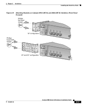
Chapter 2 Installation Installing the Switch in a Rack Figure 2-9 Attaching Brackets on Catalyst 2912 LRE XL and 2924 LRE XL Switches (Front-Panel Forward) Phillips flat-head screws Phillips truss-head screws 19" configuration INPUT OUTPUT PWR PWR RESET TEMP FAN 9X 10X 11X 12X 23" and 24" configuration INPUT OUTPUT PWR PWR RESET TEMP FAN 9X 10X 11X 12X 54728 78-6461-04 Catalyst 2900 Series XL Hardware Installation Guide 2-17
Chapter 2 Installation Installing the Switch in a Rack Figure 2-9 Attaching Brackets on Catalyst 2912 LRE XL and 2924 LRE XL Switches (Front-Panel Forward) Phillips flat-head screws Phillips truss-head screws 19" configuration INPUT OUTPUT PWR PWR RESET TEMP FAN 9X 10X 11X 12X 23" and 24" configuration INPUT OUTPUT PWR PWR RESET TEMP FAN 9X 10X 11X 12X 54728 78-6461-04 Catalyst 2900 Series XL Hardware Installation Guide 2-17