User Guide
Page 3
Contents Notices...vi Safety information vii About this guide viii P7H55/USB3 specifications summary ix Chapter 1: Product introduction 1.1 Before you proceed 1-1 1.2 Motherboard overview 1-2 1.2.1 Motherboard layout 1-2 1.2.2 Layout contents 1-2 1.3 ...1-17 1.5.4 PCI Express x1 slots 1-17 1.5.5 PCI Express 2.0 x16 slots 1-17 1.6 Jumpers 1-18 1.7 Onboard switches 1-19 1.8 Connectors 1-21 1.8.1 Rear panel connectors 1-21 1.8.2 Internal connectors 1-22 1.9 Installing an operating system 1-28 1.10 Support DVD information 1-28 1.10.1 Running the support DVD 1-28 Chapter 2: BIOS...
Contents Notices...vi Safety information vii About this guide viii P7H55/USB3 specifications summary ix Chapter 1: Product introduction 1.1 Before you proceed 1-1 1.2 Motherboard overview 1-2 1.2.1 Motherboard layout 1-2 1.2.2 Layout contents 1-2 1.3 ...1-17 1.5.4 PCI Express x1 slots 1-17 1.5.5 PCI Express 2.0 x16 slots 1-17 1.6 Jumpers 1-18 1.7 Onboard switches 1-19 1.8 Connectors 1-21 1.8.1 Rear panel connectors 1-21 1.8.2 Internal connectors 1-22 1.9 Installing an operating system 1-28 1.10 Support DVD information 1-28 1.10.1 Running the support DVD 1-28 Chapter 2: BIOS...
User Guide
Page 7
... is set to or from the system, ensure that your dealer immediately. • To avoid short circuits, keep paper clips, screws, and staples away from connectors, slots, sockets and circuitry. • Avoid dust, humidity, and temperature extremes. It could interrupt the grounding circuit. • Make sure that the power cables for...
... is set to or from the system, ensure that your dealer immediately. • To avoid short circuits, keep paper clips, screws, and staples away from connectors, slots, sockets and circuitry. • Avoid dust, humidity, and temperature extremes. It could interrupt the grounding circuit. • Make sure that the power cables for...
User Guide
Page 11
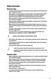
...only) User's manual Drivers ASUS Utilities ASUS Update Anti-virus software (OEM version) ATX Form Factor, 12"x 8.6" (30.5cm x 21.8cm) *Specifications are subject to change without notice. button 1 x COM connector 16 Mb Flash ROM, ...Connectors BIOS Features Manageability Accessories Support DVD Contents Form Factor 2 x USB connectors support additional 4 USB ports 6 x SATA 3Gb/s connectors 1 x 4-pin CPU Fan connector 1 x 3-pin Chassis Fan connector 1 x 3-pin Power Fan connector 1 x Front panel audio connector 1 x S/PDIF Out header 1 x CD audio in 1 Q-connector (USB, System panel; xi P7H55...
...only) User's manual Drivers ASUS Utilities ASUS Update Anti-virus software (OEM version) ATX Form Factor, 12"x 8.6" (30.5cm x 21.8cm) *Specifications are subject to change without notice. button 1 x COM connector 16 Mb Flash ROM, ...Connectors BIOS Features Manageability Accessories Support DVD Contents Form Factor 2 x USB connectors support additional 4 USB ports 6 x SATA 3Gb/s connectors 1 x 4-pin CPU Fan connector 1 x 3-pin Chassis Fan connector 1 x 3-pin Power Fan connector 1 x Front panel audio connector 1 x S/PDIF Out header 1 x CD audio in 1 Q-connector (USB, System panel; xi P7H55...
User Guide
Page 14
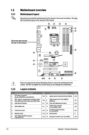
... install the motherboard into the holes indicated by circles to secure the motherboard to the rear part of the chassis. CPU, chassis, and power fan connectors (4-pin CPU_FAN, 3-pin CHA_FAN, 3-pin PWR_FAN) 3. Place this side towards the rear of the chassis. Doing so can damage the motherboard. 1.2.2 Layout contents...
... install the motherboard into the holes indicated by circles to secure the motherboard to the rear part of the chassis. CPU, chassis, and power fan connectors (4-pin CPU_FAN, 3-pin CHA_FAN, 3-pin PWR_FAN) 3. Place this side towards the rear of the chassis. Doing so can damage the motherboard. 1.2.2 Layout contents...
User Guide
Page 16
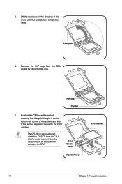
... plate is on the bottom‑left corner of the socket, and then fit the socket alignment keys into the socket to prevent bending the connectors on the socket and damaging the CPU!
... plate is on the bottom‑left corner of the socket, and then fit the socket alignment keys into the socket to prevent bending the connectors on the socket and damaging the CPU!

User Guide
Page 18
... four fasteners match the holes on top of the installed CPU, making sure that the Thermal Interface Material is properly applied to the CPU fan connector. 1-6 Chapter 1: Product introduction
... four fasteners match the holes on top of the installed CPU, making sure that the Thermal Interface Material is properly applied to the CPU fan connector. 1-6 Chapter 1: Product introduction
User Guide
Page 19
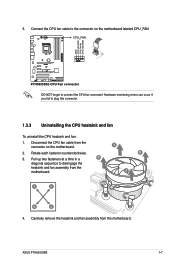
...Hardware monitoring errors can occur if you fail to connect the CPU fan connector! Carefully remove the heatsink and fan assembly from the motherboard. DO NOT forget to plug this connector. 1.3.3 Uninstalling the CPU heatsink and fan To uninstall the CPU heatsink and...fasteners at a time in a B diagonal sequence to the connector on the motherboard. 2. Rotate each fastener counterclockwise. 3. A B A A B B A 4. Disconnect the CPU fan cable from the connector on the motherboard labeled CPU_FAN. ASUS P7H55/USB3 1-7 Connect the CPU fan cable to disengage the heatsink ...
...Hardware monitoring errors can occur if you fail to connect the CPU fan connector! Carefully remove the heatsink and fan assembly from the motherboard. DO NOT forget to plug this connector. 1.3.3 Uninstalling the CPU heatsink and fan To uninstall the CPU heatsink and...fasteners at a time in a B diagonal sequence to the connector on the motherboard. 2. Rotate each fastener counterclockwise. 3. A B A A B B A 4. Disconnect the CPU fan cable from the connector on the motherboard labeled CPU_FAN. ASUS P7H55/USB3 1-7 Connect the CPU fan cable to disengage the heatsink ...
User Guide
Page 29
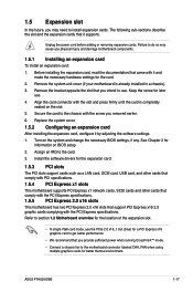
... PCIe 2.0 x16_1 slot (blue) for the card. 2. 1.5 Expansion slot In the future, you intend to use. Assign an IRQ to install expansion cards. ASUS P7H55/USB3 1-17 Before installing the expansion card, read the documentation that you physical injury and damage motherboard components. 1.5.1 Installing an expansion card To install an...the expansion cards that you may cause you provide sufficient power when running CrossFireX™ mode. • Connect a chassis fan to the motherboard connector labeled CHA_FAN when using multiple graphics cards for better thermal environment.
... PCIe 2.0 x16_1 slot (blue) for the card. 2. 1.5 Expansion slot In the future, you intend to use. Assign an IRQ to install expansion cards. ASUS P7H55/USB3 1-17 Before installing the expansion card, read the documentation that you physical injury and damage motherboard components. 1.5.1 Installing an expansion card To install an...the expansion cards that you may cause you provide sufficient power when running CrossFireX™ mode. • Connect a chassis fan to the motherboard connector labeled CHA_FAN when using multiple graphics cards for better thermal environment.
User Guide
Page 33
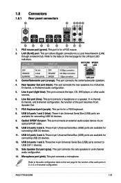
...in an 8-channel audio configuration. 14. This port connects an external audio output device via an optical S/PDIF cable. 10. 1.8 Connectors 1.8.1 Rear panel connectors 1. Line In port (light blue). USB 3.0 ports 1 and 2 (blue). This port connects the side speakers in a 4-...port connects a microphone. This port connects the center/subwoofer speakers. 4. This port connects the tape, CD, DVD player, or other audio sources. 6. ASUS P7H55/USB3 1-21 USB 2.0 ports 1 and 2. PS/2 mouse port (green). Center/Subwoofer port (orange). This port connects a headphone or a speaker....
...in an 8-channel audio configuration. 14. This port connects an external audio output device via an optical S/PDIF cable. 10. 1.8 Connectors 1.8.1 Rear panel connectors 1. Line In port (light blue). USB 3.0 ports 1 and 2 (blue). This port connects the side speakers in a 4-...port connects a microphone. This port connects the center/subwoofer speakers. 4. This port connects the tape, CD, DVD player, or other audio sources. 6. ASUS P7H55/USB3 1-21 USB 2.0 ports 1 and 2. PS/2 mouse port (green). Center/Subwoofer port (orange). This port connects a headphone or a speaker....
User Guide
Page 34
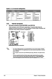
...The power supply plugs are designed to the Recommended Power Supply Wattage Calculator at http://support.asus. com/PowerSupplyCalculator/PSCalculator.aspx?SLanguage=en-us for your system, refer to fit these connectors in only one orientation. Rear Speaker Out - 6-channel Line In Front Speaker Out ...Mic In Center/Subwoofer Rear Speaker Ou - 8-channel Line In Front Speaker Out Mic In Center/Subwoofer Rear Speaker Out Side Speaker Out 1.8.2 Internal connectors 1. Otherwise, the system will not boot. • If you use a power supply unit (PSU) that complies with ATX 12 V Specification ...
...The power supply plugs are designed to the Recommended Power Supply Wattage Calculator at http://support.asus. com/PowerSupplyCalculator/PSCalculator.aspx?SLanguage=en-us for your system, refer to fit these connectors in only one orientation. Rear Speaker Out - 6-channel Line In Front Speaker Out ...Mic In Center/Subwoofer Rear Speaker Ou - 8-channel Line In Front Speaker Out Mic In Center/Subwoofer Rear Speaker Out Side Speaker Out 1.8.2 Internal connectors 1. Otherwise, the system will not boot. • If you use a power supply unit (PSU) that complies with ATX 12 V Specification ...
User Guide
Page 35
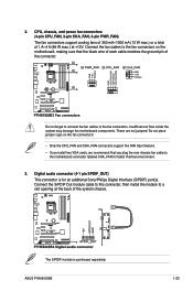
... max.) or a total of 1 A~4 A (48 W max.) at the back of the connector. Connect the fan cables to the fan connectors on the fan connectors! • Only the CPU_FAN and CHA_FAN connectors support the FAN Xpert feature. • If you install two VGA cards, we recommend that the...Connect the S/PDIF Out module cable to this connector, then install the module to the fan connectors. Do not forget to connect the fan cables to a slot opening at +12V. ASUS P7H55/USB3 1-23 Digital audio connector (4-1 pin SPDIF_OUT) This connector is purchased separately. Insufficient air flow inside the ...
... max.) or a total of 1 A~4 A (48 W max.) at the back of the connector. Connect the fan cables to the fan connectors on the fan connectors! • Only the CPU_FAN and CHA_FAN connectors support the FAN Xpert feature. • If you install two VGA cards, we recommend that the...Connect the S/PDIF Out module cable to this connector, then install the module to the fan connectors. Do not forget to connect the fan cables to a slot opening at +12V. ASUS P7H55/USB3 1-23 Digital audio connector (4-1 pin SPDIF_OUT) This connector is purchased separately. Insufficient air flow inside the ...

User Guide
Page 36
.... The COM module is for a chassis-mounted front panel audio I/O module that you connect a high-definition front panel audio module to this connector to avail of the motherboard's high-definition audio capability. • If you want to connect a high-definition front panel audio module to a... at the back of the front panel audio I/O module cable to this connector, set the item to [HD Audio]. Connect one end of the system chassis. Serial port connector (10-1 pin COM1) This connector is purchased separately. 1-24 Chapter 1: Product introduction Connect the serial port ...
.... The COM module is for a chassis-mounted front panel audio I/O module that you connect a high-definition front panel audio module to this connector to avail of the motherboard's high-definition audio capability. • If you want to connect a high-definition front panel audio module to a... at the back of the front panel audio I/O module cable to this connector, set the item to [HD Audio]. Connect one end of the system chassis. Serial port connector (10-1 pin COM1) This connector is purchased separately. 1-24 Chapter 1: Product introduction Connect the serial port ...
User Guide
Page 37
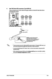
ASUS P7H55/USB3 1-25 In Standard IDE mode, you can connect Serial ATA boot/data hard disk drives to these connectors. • You must install Windows® XP Service Pack 2 or later version before using Serial ATA hard disk drives. • When using hot-plug and ...NCQ, set to [AHCI]. See section Storage Configuration for Serial ATA hard disk drives and optical disc drives. • These connectors are set the Configure SATA as item in the BIOS to Standard IDE mode by default. 6. Intel® H55 Serial ATA...
ASUS P7H55/USB3 1-25 In Standard IDE mode, you can connect Serial ATA boot/data hard disk drives to these connectors. • You must install Windows® XP Service Pack 2 or later version before using Serial ATA hard disk drives. • When using hot-plug and ...NCQ, set to [AHCI]. See section Storage Configuration for Serial ATA hard disk drives and optical disc drives. • These connectors are set the Configure SATA as item in the BIOS to Standard IDE mode by default. 6. Intel® H55 Serial ATA...
User Guide
Page 38
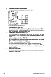
... the system is ON turns the system OFF. • Reset button (2-pin RESET) This 2-pin connector is for the chassis-mounted reset button for system reboot without turning off button (2-pin PWRSW) This connector is for the system power button. Connect the HDD Activity LED cable to the HDD. • ... depending on the system power, and blinks when the system is in sleep mode. • Hard disk drive activity LED (2-pin IDE_LED) This 2-pin connector is for the HDD Activity LED. Connect the chassis power LED cable to hear system beeps and warnings. • ATX power button/soft-off the...
... the system is ON turns the system OFF. • Reset button (2-pin RESET) This 2-pin connector is for the chassis-mounted reset button for system reboot without turning off button (2-pin PWRSW) This connector is for the system power button. Connect the HDD Activity LED cable to the HDD. • ... depending on the system power, and blinks when the system is in sleep mode. • Hard disk drive activity LED (2-pin IDE_LED) This 2-pin connector is for the HDD Activity LED. Connect the chassis power LED cable to hear system beeps and warnings. • ATX power button/soft-off the...
User Guide
Page 39
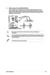
... panel USB cable to the ASUS Q-Connector (USB, blue) first, and then install the Q-Connector (USB) to 480 Mbps connection speed. Never connect a 1394 cable to a slot opening at the back of these connectors, then install the module to the USB connectors. ASUS P7H55/USB3 1-27 USB connectors (10-1 pin USB910, USB1112) These connectors are for USB 2.0 ports. Connect...
... panel USB cable to the ASUS Q-Connector (USB, blue) first, and then install the Q-Connector (USB) to 480 Mbps connection speed. Never connect a 1394 cable to a slot opening at the back of these connectors, then install the module to the USB connectors. ASUS P7H55/USB3 1-27 USB connectors (10-1 pin USB910, USB1112) These connectors are for USB 2.0 ports. Connect...
User Guide
Page 46
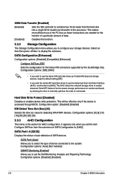
... transfer of a particular amount of data. [Disabled] Disables this item to set the item Configure SATA as [IDE] Sets the configuration for the Serial ATA connectors supported by allowing the drive to enable advanced Serial ATA features that increases storage performance on random workloads by the Southbridge chip. The AHCI allows...
... transfer of a particular amount of data. [Disabled] Disables this item to set the item Configure SATA as [IDE] Sets the configuration for the Serial ATA connectors supported by allowing the drive to enable advanced Serial ATA features that increases storage performance on random workloads by the Southbridge chip. The AHCI allows...
User Guide
Page 57
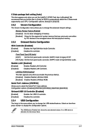
... Enabled item shows the auto-detected values. ASUS P7H55/USB3 2-17 Configuration options: [Auto] [C1] [C3] [C6] 2.5.2 Uncore Configuration The Uncore Configuration menu allows you to high-definition audio. Front Panel Type [HD Audio] [AC97] Set the front panel audio connector (AAFP) mode to legacy AC'97 [...HD Audio] Set the front panel audio connector (AAFP) mode to change the USB-related features. Realtek LAN1 [Enabled] [Enabled] Enables Realtek LAN ...
... Enabled item shows the auto-detected values. ASUS P7H55/USB3 2-17 Configuration options: [Auto] [C1] [C3] [C6] 2.5.2 Uncore Configuration The Uncore Configuration menu allows you to high-definition audio. Front Panel Type [HD Audio] [AC97] Set the front panel audio connector (AAFP) mode to legacy AC'97 [...HD Audio] Set the front panel audio connector (AAFP) mode to change the USB-related features. Realtek LAN1 [Enabled] [Enabled] Enables Realtek LAN ...


