User Guide
Page 9
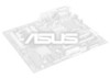
Some hyper DIMMs only support one DIMM per channel. Optical S/PDIF out port at back panel) VIA® 1708S 8-channel High Definition Audio CODEC - P7H55/USB3 specifications summary CPU Chipset Memory Expansion Slots Multi-GPU support Storage LAN USB Audio LGA1156 socket for Intel®... / 1333 MHz, non-ECC, un-buffered memory Dual channel memory architecture Supports Intel® Extreme Memory Profile (XMP) * Hyper DIMM support is subject to www.asus.com for the Memory QVL (Qualified Vendors Lists) 1 x PCI Express 2.0 x16 slot (blue) 1 x PCI Express 2.0 x16 slot (@ x4 speed, 2.5GT/s, ...
Some hyper DIMMs only support one DIMM per channel. Optical S/PDIF out port at back panel) VIA® 1708S 8-channel High Definition Audio CODEC - P7H55/USB3 specifications summary CPU Chipset Memory Expansion Slots Multi-GPU support Storage LAN USB Audio LGA1156 socket for Intel®... / 1333 MHz, non-ECC, un-buffered memory Dual channel memory architecture Supports Intel® Extreme Memory Profile (XMP) * Hyper DIMM support is subject to www.asus.com for the Memory QVL (Qualified Vendors Lists) 1 x PCI Express 2.0 x16 slot (blue) 1 x PCI Express 2.0 x16 slot (@ x4 speed, 2.5GT/s, ...
User Guide
Page 10
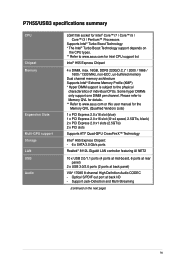
... port 6 x USB 2.0/1.1 ports 2 x USB 3.0/2.0 ports 8-channel Audio I /O Ports Hybrid Processer: - Turbo Key II Hybrid OS: - ASUS EZ Flash 2 - Multi-language BIOS Precision Tweaker 2: - vCPU PLL: 56-step reference voltage control SFS (Stepless Frequency Selection): - PCI Express frequency tuning from 80 MHz up to 500 MHz at 0.00625V increment - ASUS CrashFree BIOS 3 - ASUS My Logo 2 - P7H55/USB3 specifications summary ASUS...
... port 6 x USB 2.0/1.1 ports 2 x USB 3.0/2.0 ports 8-channel Audio I /O Ports Hybrid Processer: - Turbo Key II Hybrid OS: - ASUS EZ Flash 2 - Multi-language BIOS Precision Tweaker 2: - vCPU PLL: 56-step reference voltage control SFS (Stepless Frequency Selection): - PCI Express frequency tuning from 80 MHz up to 500 MHz at 0.00625V increment - ASUS CrashFree BIOS 3 - ASUS My Logo 2 - P7H55/USB3 specifications summary ASUS...
User Guide
Page 11
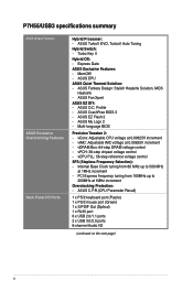
xi P7H55/USB3 specifications summary Internal I /O shield 2 in 1 x 24-pin EATX ...Serial ATA 3.0Gb/s cables 1 x I /O Connectors BIOS Features Manageability Accessories Support DVD Contents Form Factor 2 x USB connectors support additional 4 USB ports 6 x SATA 3Gb/s connectors 1 x 4-pin CPU Fan connector 1 x 3-pin Chassis Fan connector 1 x 3-pin Power Fan connector 1 ...x CD audio in 1 Q-connector (USB, System panel; Retail version only) User's manual Drivers ASUS Utilities ASUS Update Anti-virus software (OEM version) ATX Form Factor, 12"x 8.6" (30.5cm x 21.8cm) *Specifications are subject ...
xi P7H55/USB3 specifications summary Internal I /O shield 2 in 1 x 24-pin EATX ...Serial ATA 3.0Gb/s cables 1 x I /O Connectors BIOS Features Manageability Accessories Support DVD Contents Form Factor 2 x USB connectors support additional 4 USB ports 6 x SATA 3Gb/s connectors 1 x 4-pin CPU Fan connector 1 x 3-pin Chassis Fan connector 1 x 3-pin Power Fan connector 1 ...x CD audio in 1 Q-connector (USB, System panel; Retail version only) User's manual Drivers ASUS Utilities ASUS Update Anti-virus software (OEM version) ATX Form Factor, 12"x 8.6" (30.5cm x 21.8cm) *Specifications are subject ...
User Guide
Page 14
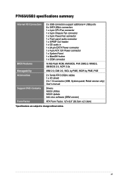
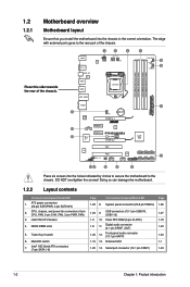
...LED Page 1-22 8. System panel connector (20-8 pin PANEL) 1-26 1-23 9. Digital audio connector (4-1 pin SPDIF_OUT) 1-23 1-20 12. Serial port connector (10-1 pin COM1) 1-24 1-2 Chapter 1: Product introduction DO NOT overtighten the screws! DDR3 DIMM slots 5. Front panel audio connector (10-1... RTC RAM (3-pin CLRTC) 1-18 1-8 11. Place this side towards the rear of the chassis. MemOK! The edge with external ports goes to the chassis. Doing so can damage the motherboard. 1.2.2 Layout contents Connectors/Jumpers/Slots/LED 1. 1.2 1.2.1 Motherboard overview Motherboard ...
...LED Page 1-22 8. System panel connector (20-8 pin PANEL) 1-26 1-23 9. Digital audio connector (4-1 pin SPDIF_OUT) 1-23 1-20 12. Serial port connector (10-1 pin COM1) 1-24 1-2 Chapter 1: Product introduction DO NOT overtighten the screws! DDR3 DIMM slots 5. Front panel audio connector (10-1... RTC RAM (3-pin CLRTC) 1-18 1-8 11. Place this side towards the rear of the chassis. MemOK! The edge with external ports goes to the chassis. Doing so can damage the motherboard. 1.2.2 Layout contents Connectors/Jumpers/Slots/LED 1. 1.2 1.2.1 Motherboard overview Motherboard ...
User Guide
Page 33
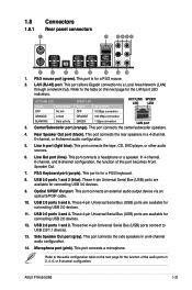
... Universal Serial Bus (USB) ports are available for the function of this port becomes Front Speaker Out. 7. This port connects a microphone. ASUS P7H55/USB3 1-21 This port allows Gigabit connection to USB 2.0/1.1 devices. 13. Optical S/PDIF Out port. PS/2 mouse port (green). LAN (RJ-45) port. This port is for the LAN port LED indicators. This port connects the tape, CD, DVD...
... Universal Serial Bus (USB) ports are available for the function of this port becomes Front Speaker Out. 7. This port connects a microphone. ASUS P7H55/USB3 1-21 This port allows Gigabit connection to USB 2.0/1.1 devices. 13. Optical S/PDIF Out port. PS/2 mouse port (green). LAN (RJ-45) port. This port is for the LAN port LED indicators. This port connects the tape, CD, DVD...
User Guide
Page 34
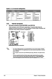
... minimum power supply requirement for your system, refer to the Recommended Power Supply Wattage Calculator at http://support.asus. com/PowerSupplyCalculator/PSCalculator.aspx?SLanguage=en-us for ATX power supply plugs. Audio 2, 4, 6, 8-channel configuration Port Light Blue Lime Pink Orange Black Gray Headset 2-channel Line In Line Out Mic In - - - 4-channel Line...
... minimum power supply requirement for your system, refer to the Recommended Power Supply Wattage Calculator at http://support.asus. com/PowerSupplyCalculator/PSCalculator.aspx?SLanguage=en-us for ATX power supply plugs. Audio 2, 4, 6, 8-channel configuration Port Light Blue Lime Pink Orange Black Gray Headset 2-channel Line In Line Out Mic In - - - 4-channel Line...
User Guide
Page 35
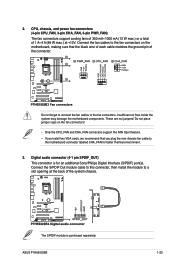
... Interface (S/PDIF) port(s). Insufficient air flow inside the system may damage the motherboard components. These are not jumpers! The S/PDIF module is for better thermal environment. 3. Do not forget to connect the fan cables to a slot opening at +12V. Digital audio connector (4-1 pin SPDIF_OUT) This connector is purchased separately. ASUS P7H55/USB3 1-23...
... Interface (S/PDIF) port(s). Insufficient air flow inside the system may damage the motherboard components. These are not jumpers! The S/PDIF module is for better thermal environment. 3. Do not forget to connect the fan cables to a slot opening at +12V. Digital audio connector (4-1 pin SPDIF_OUT) This connector is purchased separately. ASUS P7H55/USB3 1-23...

User Guide
Page 36
... set the item to this connector, set the Front Panel Type item in the BIOS setup to avail of the system chassis. Connect the serial port module cable to this connector, then install the module to a slot opening at the back of the motherboard's high-definition audio capability. • If you... connect a high-definition front panel audio module to this connector is for a serial (COM) port. Serial port connector (10-1 pin COM1) This connector is purchased separately. 1-24 Chapter 1: Product introduction 4.
... set the item to this connector, set the Front Panel Type item in the BIOS setup to avail of the system chassis. Connect the serial port module cable to this connector, then install the module to a slot opening at the back of the motherboard's high-definition audio capability. • If you... connect a high-definition front panel audio module to this connector is for a serial (COM) port. Serial port connector (10-1 pin COM1) This connector is purchased separately. 1-24 Chapter 1: Product introduction 4.
User Guide
Page 39
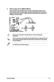
... any of these connectors, then install the module to the USB connector onboard if your chassis supports front panel USB ports. You can connect the front panel USB cable to the ASUS Q-Connector (USB, blue) first, and then install the Q-Connector (USB) to a slot opening at the back of the system... separately. These USB connectors comply with USB 2.0 specification that supports up to the USB connectors. Never connect a 1394 cable to 480 Mbps connection speed. ASUS P7H55/USB3 1-27 Doing so will damage the motherboard! USB connectors (10-1 pin USB910, USB1112) These connectors are for USB...
... any of these connectors, then install the module to the USB connector onboard if your chassis supports front panel USB ports. You can connect the front panel USB cable to the ASUS Q-Connector (USB, blue) first, and then install the Q-Connector (USB) to a slot opening at the back of the system... separately. These USB connectors comply with USB 2.0 specification that supports up to the USB connectors. Never connect a 1394 cable to 480 Mbps connection speed. ASUS P7H55/USB3 1-27 Doing so will damage the motherboard! USB connectors (10-1 pin USB910, USB1112) These connectors are for USB...
User Guide
Page 42
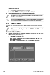
b. See section Exit Menu for details. 2.1.2 ASUS EZ Flash 2 The ASUS EZ Flash 2 feature allows you start using EZ Flash 2: 1. Before you to complete the update process. ASUSTek EZ Flash 2 BIOS ROM Utility V4.12 Current ROM BOARD: P7H55-USB3 VER: 0108 DATE: 04/21/2010 Update ROM BOARD: Unknown ...onscreen instructions to update the BIOS without using an OS‑based utility. Press to the USB port, then launch EZ Flash 2 in any of updating itself through the Internet. The ASUS Update utility is found. Insert the USB flash disk that contains the latest BIOS file to ...
b. See section Exit Menu for details. 2.1.2 ASUS EZ Flash 2 The ASUS EZ Flash 2 feature allows you start using EZ Flash 2: 1. Before you to complete the update process. ASUSTek EZ Flash 2 BIOS ROM Utility V4.12 Current ROM BOARD: P7H55-USB3 VER: 0108 DATE: 04/21/2010 Update ROM BOARD: Unknown ...onscreen instructions to update the BIOS without using an OS‑based utility. Press to the USB port, then launch EZ Flash 2 in any of updating itself through the Internet. The ASUS Update utility is found. Insert the USB flash disk that contains the latest BIOS file to ...
User Guide
Page 43
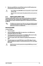
... or reset the system while updating the BIOS to use the newer BIOS file, download the file at support.asus.com and save it fails or gets corrupted during the updating process. ASUS P7H55/USB3 2-3 You can restore a corrupted BIOS file using the motherboard support DVD or a USB flash drive that you... automatically checks the devices for the BIOS file. When the correct BIOS file is an auto recovery tool that allows you press to the USB port. 3. Turn on again. 5. Turn off the system after the utility completes the updating process and power on the system. 2. When found , EZ Flash 2 ...
... or reset the system while updating the BIOS to use the newer BIOS file, download the file at support.asus.com and save it fails or gets corrupted during the updating process. ASUS P7H55/USB3 2-3 You can restore a corrupted BIOS file using the motherboard support DVD or a USB flash drive that you... automatically checks the devices for the BIOS file. When the correct BIOS file is an auto recovery tool that allows you press to the USB port. 3. Turn on again. 5. Turn off the system after the utility completes the updating process and power on the system. 2. When found , EZ Flash 2 ...


