User Guide
Page 6
...pursuant to Part 15 of the monitor to the graphics card is required to assure compliance with FCC regulations. The use of shielded cables for disposal of the FCC Rules. Check local regulations for connection of the FCC Rules. vi Notices Federal Communications Commission Statement This ...has been designed to which can radiate radio frequency energy and, if not installed and used in our products at ASUS REACH website at http://green.asus.com/english/REACH.htm. REACH Complying with Canadian ICES-003. Canadian Department of Communications Statement This digital apparatus does...
...pursuant to Part 15 of the monitor to the graphics card is required to assure compliance with FCC regulations. The use of shielded cables for disposal of the FCC Rules. Check local regulations for connection of the FCC Rules. vi Notices Federal Communications Commission Statement This ...has been designed to which can radiate radio frequency energy and, if not installed and used in our products at ASUS REACH website at http://green.asus.com/english/REACH.htm. REACH Complying with Canadian ICES-003. Canadian Department of Communications Statement This digital apparatus does...
User Guide
Page 7
...substances into the environment. • Never dispose of the electrical outlet you detect any area where it , carefully read all power cables are connected. Take it by yourself. INVISIBLE LASER RADIATION, AVOID EXPOSURE TO BEAM. • Never dispose of the battery in...become wet. • Place the product on a stable surface. • If you add a device. • Before connecting or removing signal cables from connectors, slots, sockets and circuitry. • Avoid dust, humidity, and temperature extremes. Operation safety • Before installing the motherboard and ...
...substances into the environment. • Never dispose of the electrical outlet you detect any area where it , carefully read all power cables are connected. Take it by yourself. INVISIBLE LASER RADIATION, AVOID EXPOSURE TO BEAM. • Never dispose of the battery in...become wet. • Place the product on a stable surface. • If you add a device. • Before connecting or removing signal cables from connectors, slots, sockets and circuitry. • Avoid dust, humidity, and temperature extremes. Operation safety • Before installing the motherboard and ...
User Guide
Page 11
Retail version only) User's manual Drivers ASUS Utilities ASUS Update Anti-virus software (OEM version) ATX Form Factor, 12"x 8.6" (30.5cm x 21.8cm) *Specifications are subject to change without notice. xi .../s cables 1 x I /O Connectors BIOS Features Manageability Accessories Support DVD Contents Form Factor 2 x USB connectors support additional 4 USB ports 6 x SATA 3Gb/s connectors 1 x 4-pin CPU Fan connector 1 x 3-pin Chassis Fan connector 1 x 3-pin Power Fan connector 1 x Front panel audio connector 1 x S/PDIF Out header 1 x CD audio in 1 Q-connector (USB, System panel; P7H55/USB3...
Retail version only) User's manual Drivers ASUS Utilities ASUS Update Anti-virus software (OEM version) ATX Form Factor, 12"x 8.6" (30.5cm x 21.8cm) *Specifications are subject to change without notice. xi .../s cables 1 x I /O Connectors BIOS Features Manageability Accessories Support DVD Contents Form Factor 2 x USB connectors support additional 4 USB ports 6 x SATA 3Gb/s connectors 1 x 4-pin CPU Fan connector 1 x 3-pin Chassis Fan connector 1 x 3-pin Power Fan connector 1 x Front panel audio connector 1 x S/PDIF Out header 1 x CD audio in 1 Q-connector (USB, System panel; P7H55/USB3...
User Guide
Page 13
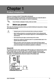
...you uninstall any of the items is damaged or missing, contact your motherboard package. The illustration below shows the location of the onboard LED. ASUS P7H55/USB3 1-1 Onboard LED The motherboard comes with the component. • Before you install or remove any component, ensure that the ATX power ...in the bag that came with a standby power LED that lights up to indicate that you must shut down the system and unplug the power cable before touching any component. • Before handling components, use a grounded wrist strap or touch a safely grounded object or a metal object,...
...you uninstall any of the items is damaged or missing, contact your motherboard package. The illustration below shows the location of the onboard LED. ASUS P7H55/USB3 1-1 Onboard LED The motherboard comes with the component. • Before you install or remove any component, ensure that the ATX power ...in the bag that came with a standby power LED that lights up to indicate that you must shut down the system and unplug the power cable before touching any component. • Before handling components, use a grounded wrist strap or touch a safely grounded object or a metal object,...
User Guide
Page 15
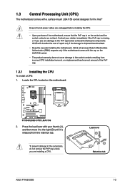
...) The motherboard comes with a surface mount LGA1156 socket designed for the Intel® Ensure that all power cables are unplugged before installing the CPU. • Upon purchase of the PnP cap. 1.3.1 Installing the CPU To...you see any damage to the socket contacts resulting from the retention tab. ASUS will shoulder the cost of repair only if the damage is on the socket and the socket ...contacts are installing a CPU. ASUS will process Return Merchandise Authorization (RMA) requests only if the motherboard comes with your retailer...
...) The motherboard comes with a surface mount LGA1156 socket designed for the Intel® Ensure that all power cables are unplugged before installing the CPU. • Upon purchase of the PnP cap. 1.3.1 Installing the CPU To...you see any damage to the socket contacts resulting from the retention tab. ASUS will shoulder the cost of repair only if the damage is on the socket and the socket ...contacts are installing a CPU. ASUS will process Return Merchandise Authorization (RMA) requests only if the motherboard comes with your retailer...

User Guide
Page 18
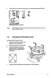
... the heatsink and fan assembly such that the four fasteners match the holes on top of the installed CPU, making sure that the CPU fan cable is incompatible with the LGA775 and LGA1366 sockets in place. Ensure that you have installed the motherboard to the chassis before you use only Intel...
... the heatsink and fan assembly such that the four fasteners match the holes on top of the installed CPU, making sure that the CPU fan cable is incompatible with the LGA775 and LGA1366 sockets in place. Ensure that you have installed the motherboard to the chassis before you use only Intel...
User Guide
Page 19
... the CPU heatsink and fan To uninstall the CPU heatsink and fan: 1. Rotate each fastener counterclockwise. 3. A B A A B B A 4. ASUS P7H55/USB3 1-7 3. Hardware monitoring errors can occur if you fail to connect the CPU fan connector! Carefully remove the heatsink and fan assembly from the motherboard.... Disconnect the CPU fan cable from the connector on the motherboard labeled CPU_FAN. Pull up two fasteners at a time in a B diagonal sequence to the ...
... the CPU heatsink and fan To uninstall the CPU heatsink and fan: 1. Rotate each fastener counterclockwise. 3. A B A A B B A 4. ASUS P7H55/USB3 1-7 3. Hardware monitoring errors can occur if you fail to connect the CPU fan connector! Carefully remove the heatsink and fan assembly from the motherboard.... Disconnect the CPU fan cable from the connector on the motherboard labeled CPU_FAN. Pull up two fasteners at a time in a B diagonal sequence to the ...
User Guide
Page 33
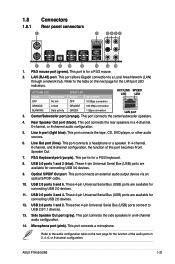
... port connects a headphone or a speaker. USB 3.0 ports 1 and 2 (blue). This port connects an external audio output device via an optical S/PDIF cable. 10. USB 2.0 ports 1 and 2. Microphone port (pink). ASUS P7H55/USB3 1-21 LAN (RJ-45) port. This port connects a microphone. Refer to a Local Area Network (LAN) through a network hub. ACT/LINK LED...
... port connects a headphone or a speaker. USB 3.0 ports 1 and 2 (blue). This port connects an external audio output device via an optical S/PDIF cable. 10. USB 2.0 ports 1 and 2. Microphone port (pink). ASUS P7H55/USB3 1-21 LAN (RJ-45) port. This port connects a microphone. Refer to a Local Area Network (LAN) through a network hub. ACT/LINK LED...
User Guide
Page 35
...! 2. Connect the fan cables to the fan connectors. CPU, chassis, and power fan connectors (4-pin CPU_FAN, 3-pin CHA_FAN, 3-pin PWR_FAN) The fan connectors support cooling fans of 350 mA~1000 mA (12 W max.) or a total of 1 A~4 A (48 W max.) at the back of the connector. ASUS P7H55/USB3 1-23 Do not... forget to connect the fan cables to the fan connectors on the fan connectors! • Only the CPU_FAN and CHA_FAN connectors support the FAN Xpert feature. •...
...! 2. Connect the fan cables to the fan connectors. CPU, chassis, and power fan connectors (4-pin CPU_FAN, 3-pin CHA_FAN, 3-pin PWR_FAN) The fan connectors support cooling fans of 350 mA~1000 mA (12 W max.) or a total of 1 A~4 A (48 W max.) at the back of the connector. ASUS P7H55/USB3 1-23 Do not... forget to connect the fan cables to the fan connectors on the fan connectors! • Only the CPU_FAN and CHA_FAN connectors support the FAN Xpert feature. •...

User Guide
Page 36
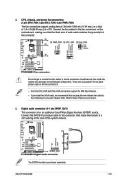
By default, this connector is for a serial (COM) port. The COM module is for a chassis-mounted front panel audio I /O module cable to this connector, then install the module to [HD Audio]. 5. 4. Front panel audio connector (10-1 pin AAFP) This connector is set the item to [HD... Audio]. Connect the serial port module cable to this connector. • We recommend that supports either HD Audio or legacy AC`97 audio standard. If you want to connect a high-definition front...
By default, this connector is for a serial (COM) port. The COM module is for a chassis-mounted front panel audio I /O module cable to this connector, then install the module to [HD Audio]. 5. 4. Front panel audio connector (10-1 pin AAFP) This connector is set the item to [HD... Audio]. Connect the serial port module cable to this connector. • We recommend that supports either HD Audio or legacy AC`97 audio standard. If you want to connect a high-definition front...
User Guide
Page 37
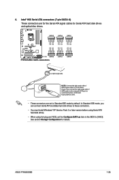
6. ASUS P7H55/USB3 1-25 In Standard IDE mode, you can connect Serial ATA boot/data hard disk drives to these connectors. • You must install Windows® ... in the BIOS to Standard IDE mode by default. Intel® H55 Serial ATA connectors (7-pin SATA1-6) These connectors are for the Serial ATA signal cables for details.
6. ASUS P7H55/USB3 1-25 In Standard IDE mode, you can connect Serial ATA boot/data hard disk drives to these connectors. • You must install Windows® ... in the BIOS to Standard IDE mode by default. Intel® H55 Serial ATA connectors (7-pin SATA1-6) These connectors are for the Serial ATA signal cables for details.
User Guide
Page 38
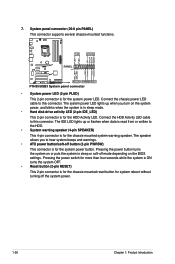
Connect the HDD Activity LED cable to this connector. Pressing the power button turns the system on or puts the system in sleep mode. • Hard disk drive activity LED (2-pin ... chassis-mounted functions. • System power LED (2-pin PLED) This 2-pin connector is for the chassis-mounted system warning speaker. Connect the chassis power LED cable to this connector. Pressing the power switch for more than four seconds while the system is ON turns the system OFF. • Reset button (2-pin...
Connect the HDD Activity LED cable to this connector. Pressing the power button turns the system on or puts the system in sleep mode. • Hard disk drive activity LED (2-pin ... chassis-mounted functions. • System power LED (2-pin PLED) This 2-pin connector is for the chassis-mounted system warning speaker. Connect the chassis power LED cable to this connector. Pressing the power switch for more than four seconds while the system is ON turns the system OFF. • Reset button (2-pin...
User Guide
Page 39
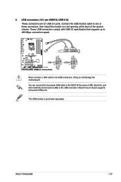
... ports. Doing so will damage the motherboard! You can connect the front panel USB cable to the ASUS Q-Connector (USB, blue) first, and then install the Q-Connector (USB) to the USB connectors. The USB module is purchased separately. 8. ASUS P7H55/USB3 1-27 USB connectors (10-1 pin USB910, USB1112) These connectors are for USB 2.0 ports...
... ports. Doing so will damage the motherboard! You can connect the front panel USB cable to the ASUS Q-Connector (USB, blue) first, and then install the Q-Connector (USB) to the USB connectors. The USB module is purchased separately. 8. ASUS P7H55/USB3 1-27 USB connectors (10-1 pin USB910, USB1112) These connectors are for USB 2.0 ports...
User Guide
Page 65
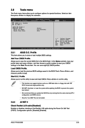
...cable during the Power-On Self‑Test (POST). Press , and choose a profile to Sub Screen F1 General Help F10 Save and Exit ESC Exit v02.61 (C)Copyright 1985-2010, American Megatrends, Inc. 2.8.1 ASUS O.C. Press to run the utility to save your CMOS settings in the BIOS Flash. Configuration options: [Disabled] [Enabled] ASUS P7H55.../USB3 2-25 Select an item then press to configure options for special functions. Main Ai Tweaker BIOS SETUP UTILITY Advanced Power Boot ASUS O.C. Profile This item allows you to ...
...cable during the Power-On Self‑Test (POST). Press , and choose a profile to Sub Screen F1 General Help F10 Save and Exit ESC Exit v02.61 (C)Copyright 1985-2010, American Megatrends, Inc. 2.8.1 ASUS O.C. Press to run the utility to save your CMOS settings in the BIOS Flash. Configuration options: [Disabled] [Enabled] ASUS P7H55.../USB3 2-25 Select an item then press to configure options for special functions. Main Ai Tweaker BIOS SETUP UTILITY Advanced Power Boot ASUS O.C. Profile This item allows you to ...


