

User Manual
Page 1
Motherboard P5G41-M LX2 Series • P5G41-M LX2 • P5G41-M LX2/GB
Motherboard P5G41-M LX2 Series • P5G41-M LX2 • P5G41-M LX2/GB

User Manual
Page 3
Contents Notices...v Safety information vi About this guide vi P5G41-M LX2 Series specifications summary viii Chapter 1: Product introduction 1.1 Before you proceed 1-1 1.2 Motherboard overview 1-2 1.2.1 Motherboard layout 1-2 1.2.2 Layout contents 1-2 1.3 Central Processing Unit (CPU 1-3 1.4 System memory 1-3 1.4.1 Overview 1-3 1.4.2 Memory configurations 1-4 1.5 Expansion ... DVD information 1-17 Chapter 2: BIOS information 2.1 Managing and updating your BIOS 2-1 2.1.1 ASUS Update utility 2-1 2.1.2 ASUS EZ Flash 2 2-2 2.1.3 ASUS CrashFree BIOS 2-3 2.2 BIOS setup program 2-3 iii
Contents Notices...v Safety information vi About this guide vi P5G41-M LX2 Series specifications summary viii Chapter 1: Product introduction 1.1 Before you proceed 1-1 1.2 Motherboard overview 1-2 1.2.1 Motherboard layout 1-2 1.2.2 Layout contents 1-2 1.3 Central Processing Unit (CPU 1-3 1.4 System memory 1-3 1.4.1 Overview 1-3 1.4.2 Memory configurations 1-4 1.5 Expansion ... DVD information 1-17 Chapter 2: BIOS information 2.1 Managing and updating your BIOS 2-1 2.1.1 ASUS Update utility 2-1 2.1.2 ASUS EZ Flash 2 2-2 2.1.3 ASUS CrashFree BIOS 2-3 2.2 BIOS setup program 2-3 iii
User Manual
Page 5
...interference received including interference that the product (electrical and electronic equipment) should not be placed in our products at ASUS REACH website at http://green.asus.com/english/REACH.htm. This symbol of Communications Statement This digital apparatus does not exceed the Class B limits for.... This symbol of the crossed out wheeled bin indicates that interference will not occur in municipal waste. DO NOT throw the motherboard in municipal waste. Notices Federal Communications Commission Statement This device complies with Part 15 of the FCC Rules. This equipment has ...
...interference received including interference that the product (electrical and electronic equipment) should not be placed in our products at ASUS REACH website at http://green.asus.com/english/REACH.htm. This symbol of Communications Statement This digital apparatus does not exceed the Class B limits for.... This symbol of the crossed out wheeled bin indicates that interference will not occur in municipal waste. DO NOT throw the motherboard in municipal waste. Notices Federal Communications Commission Statement This device complies with Part 15 of the FCC Rules. This equipment has ...

User Manual
Page 6
...are not sure about the voltage of the electrical outlet you need when installing and configuring the motherboard. If you add a device. • Before connecting or removing signal cables from the motherboard, ensure that all the manuals that came with the product, contact a qualified service technician ...or extension cord. About this guide is set to the correct voltage in any damage, contact your area. Detailed descriptions of the motherboard and the new technology it by yourself. If possible, disconnect all power cables from the existing system before you detect any area ...
...are not sure about the voltage of the electrical outlet you need when installing and configuring the motherboard. If you add a device. • Before connecting or removing signal cables from the motherboard, ensure that all the manuals that came with the product, contact a qualified service technician ...or extension cord. About this guide is set to the correct voltage in any damage, contact your area. Detailed descriptions of the motherboard and the new technology it by yourself. If possible, disconnect all power cables from the existing system before you detect any area ...
User Manual
Page 10
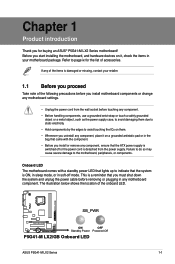
... • Whenever you install motherboard components or change any motherboard settings. • Unplug the power cord from the power supply. SB_PWR P5G41-M LX2/GB ON OFF Standby Power Powered Off P5G41-M LX2/GB Onboard LED ASUS P5G41-M LX2 Series 1-1 Before you start installing the motherboard, and hardware devices on a... 1 Product introduction Thank you for the list of accessories. Refer to page ix for buying an ASUS® P5G41-M LX2 Series motherboard! Onboard LED The motherboard comes with the component. • Before you install or remove any component, ensure that the ATX...
... • Whenever you install motherboard components or change any motherboard settings. • Unplug the power cord from the power supply. SB_PWR P5G41-M LX2/GB ON OFF Standby Power Powered Off P5G41-M LX2/GB Onboard LED ASUS P5G41-M LX2 Series 1-1 Before you start installing the motherboard, and hardware devices on a... 1 Product introduction Thank you for the list of accessories. Refer to page ix for buying an ASUS® P5G41-M LX2 Series motherboard! Onboard LED The motherboard comes with the component. • Before you install or remove any component, ensure that the ATX...
User Manual
Page 11
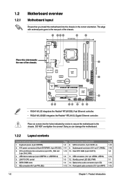
...power (3-pin KBPWR) 2. Optical drive audio connector (4-pin CD) 1-13 14. USB device wake-up (3-pin USBPW1-4, USBPW5-8) 5. Doing so can damage the motherboard. 1.2.2 Layout contents Connectors/Jumpers/Slots/LED 1. ATX power connectors (24-pin EATXPWR, 4-pin ATX12V) 3. Clear RTC RAM (3-pin CLRTC) 1-9 11. SATA... Intel® G41 PCIEX1 Lithium Cell CMOS Power PRI_IDE 7 2 24.4cm(9.6in) EATXPWR Super I/O VIA VT1705 CD AAFP PCIEX16 P5G41-M LX2/GB PCI1 Intel® ICH7 SATA4 SATA3 SATA2 SATA1 8Mb BIOS PCI2 8 SB_PWR USBPW5-8 USB56 USB78 CLRTC F_PANEL 14 13 4 12 11 10 9...
...power (3-pin KBPWR) 2. Optical drive audio connector (4-pin CD) 1-13 14. USB device wake-up (3-pin USBPW1-4, USBPW5-8) 5. Doing so can damage the motherboard. 1.2.2 Layout contents Connectors/Jumpers/Slots/LED 1. ATX power connectors (24-pin EATXPWR, 4-pin ATX12V) 3. Clear RTC RAM (3-pin CLRTC) 1-9 11. SATA... Intel® G41 PCIEX1 Lithium Cell CMOS Power PRI_IDE 7 2 24.4cm(9.6in) EATXPWR Super I/O VIA VT1705 CD AAFP PCIEX16 P5G41-M LX2/GB PCI1 Intel® ICH7 SATA4 SATA3 SATA2 SATA1 8Mb BIOS PCI2 8 SB_PWR USBPW5-8 USB56 USB78 CLRTC F_PANEL 14 13 4 12 11 10 9...
User Manual
Page 12
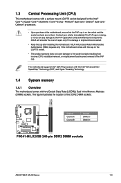
... Authorization (RMA) requests only if the motherboard comes with the cap on the socket and the socket contacts are not bent. The figure illustrates the location of the DDR2 DIMM sockets: DIMM_A1 DIMM_B1 P5G41-M LX2/GB Channel Channel A Channel B Sockets DIMM_A1 DIMM_B1 P5G41-M LX2/GB 240-pin DDR2 DIMM sockets ASUS P5G41-M LX2 Series 1-3 ASUS will shoulder the cost of repair...
... Authorization (RMA) requests only if the motherboard comes with the cap on the socket and the socket contacts are not bent. The figure illustrates the location of the DDR2 DIMM sockets: DIMM_A1 DIMM_B1 P5G41-M LX2/GB Channel Channel A Channel B Sockets DIMM_A1 DIMM_B1 P5G41-M LX2/GB 240-pin DDR2 DIMM sockets ASUS P5G41-M LX2 Series 1-3 ASUS will shoulder the cost of repair...
User Manual
Page 13
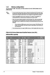
... Transcend JM667QLJ-1G 1024MB DS Transcend JM667QLU-2G 2048MB DS Twinmos 8D-A3JK5MPETP 512MB SS Chip Brand Chip NO. P5G41-M LX2 Series Motherboard Qualified Vendors Lists (QVL) DDR2-667MHz capability Vendor Part No. Size SS/ DS A-Data M2OAD5H3J4170I1C53 2048MB DS ... a 32-bit Windows® OS. - Install a 64-bit Windows® OS when you want to the memory address limitation on the motherboard. • This motherboard does not support DIMMs made up of 256 megabits (Mb) chips or less. Corsair MIII0052532M8CEC - - G.SKILL D2 64M8CCF 0815 C7173S 5-5-5-15 ...
... Transcend JM667QLJ-1G 1024MB DS Transcend JM667QLU-2G 2048MB DS Twinmos 8D-A3JK5MPETP 512MB SS Chip Brand Chip NO. P5G41-M LX2 Series Motherboard Qualified Vendors Lists (QVL) DDR2-667MHz capability Vendor Part No. Size SS/ DS A-Data M2OAD5H3J4170I1C53 2048MB DS ... a 32-bit Windows® OS. - Install a 64-bit Windows® OS when you want to the memory address limitation on the motherboard. • This motherboard does not support DIMMs made up of 256 megabits (Mb) chips or less. Corsair MIII0052532M8CEC - - G.SKILL D2 64M8CCF 0815 C7173S 5-5-5-15 ...
User Manual
Page 16
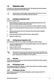
... . 4. Remove the system unit cover (if your motherboard is completely seated on shared slots, ensure that the drivers support "Share IRQ" or that they support. Install the software drivers for later use . ASUS P5G41-M LX2 Series 1-7 The following sub‑sections describe the slots...slot that complies with the PCI Express specifications. Align the card connector with the PCI Express specifications. 1.5.5 PCI Express x16 slot This motherboard supports a PCI Express x16 graphics card that you removed earlier. 6. See Chapter 2 for the card. 2. Turn on BIOS setup....
... . 4. Remove the system unit cover (if your motherboard is completely seated on shared slots, ensure that the drivers support "Share IRQ" or that they support. Install the software drivers for later use . ASUS P5G41-M LX2 Series 1-7 The following sub‑sections describe the slots...slot that complies with the PCI Express specifications. Align the card connector with the PCI Express specifications. 1.5.5 PCI Express x16 slot This motherboard supports a PCI Express x16 graphics card that you removed earlier. 6. See Chapter 2 for the card. 2. Turn on BIOS setup....
User Manual
Page 21
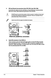
... signal cables for Serial ATA 3Gb/s hard disk drives and optical disk drives. Only the 4-pin CPU fan supports the ASUS Q-Fan feature. DO NOT forget to connect the fan cables to the fan connectors on the fan connectors! The data transfer... GND GND RSATA_RXN1 RSATA_RXP1 GND RSATA_TXN1 RSATA_TXP1 GND P5G41-M LX2/GB SATA2 SATA1 P5G41-M LX2/GB SATA connectors 1-12 Chapter 1: Product introduction 2. Insufficient air flow inside the system may damage the motherboard components. Do not place jumper caps on the motherboard, ensuring that the black wire of each cable...
... signal cables for Serial ATA 3Gb/s hard disk drives and optical disk drives. Only the 4-pin CPU fan supports the ASUS Q-Fan feature. DO NOT forget to connect the fan cables to the fan connectors on the fan connectors! The data transfer... GND GND RSATA_RXN1 RSATA_RXP1 GND RSATA_TXN1 RSATA_TXP1 GND P5G41-M LX2/GB SATA2 SATA1 P5G41-M LX2/GB SATA connectors 1-12 Chapter 1: Product introduction 2. Insufficient air flow inside the system may damage the motherboard components. Do not place jumper caps on the motherboard, ensuring that the black wire of each cable...
User Manual
Page 22
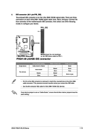
... P5G41-M LX2/GB IDE connector Single device Two devices Drive jumper setting Cable-Select or Master Cable-Select Master Slave Mode of the following modes to PIN 1. If any device jumper is removed to match the covered hole on each Ultra DMA 100/66 signal cable: blue, black, and gray. ASUS P5G41-M LX2...the IDE cable. • Use the 80-conductor IDE cable for the Ultra DMA 100/66 signal cable. Connect the blue connector to the motherboard's IDE connector, then select one of device(s) - Master Slave Master Slave Cable connector Black Black Gray Black or gray • Pin 20 ...
... P5G41-M LX2/GB IDE connector Single device Two devices Drive jumper setting Cable-Select or Master Cable-Select Master Slave Mode of the following modes to PIN 1. If any device jumper is removed to match the covered hole on each Ultra DMA 100/66 signal cable: blue, black, and gray. ASUS P5G41-M LX2...the IDE cable. • Use the 80-conductor IDE cable for the Ultra DMA 100/66 signal cable. Connect the blue connector to the motherboard's IDE connector, then select one of device(s) - Master Slave Master Slave Cable connector Black Black Gray Black or gray • Pin 20 ...
User Manual
Page 23
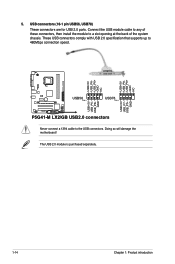
...+5V USB_P8USB_P8+ GND NC USB+5V USB_P6USB_P6+ GND NC P5G41-M LX2/GB USB56 PIN 1 USB78 PIN 1 USB+5V USB_P7USB_P7+ GND USB+5V USB_P5USB_P5+ GND P5G41-M LX2/GB USB2.0 connectors Never connect a 1394 cable to a slot opening at the back of the system chassis. Doing so will damage the motherboard! The USB 2.0 module is purchased separately. 1-14 Chapter...
...+5V USB_P8USB_P8+ GND NC USB+5V USB_P6USB_P6+ GND NC P5G41-M LX2/GB USB56 PIN 1 USB78 PIN 1 USB+5V USB_P7USB_P7+ GND USB+5V USB_P5USB_P5+ GND P5G41-M LX2/GB USB2.0 connectors Never connect a 1394 cable to a slot opening at the back of the system chassis. Doing so will damage the motherboard! The USB 2.0 module is purchased separately. 1-14 Chapter...
User Manual
Page 24
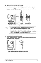
...front panel audio I /O module cable to this connector is for details. 7. CD Right Audio Channel GND GND Left Audio Channel P5G41-M LX2/GB P5G41-M LX2/GB Internal audio connector ASUS P5G41-M LX2 Series 1-15 Front panel audio connector (10-1 pin AAFP) This connector is set the item to [HD Audio]. If you...the front panel audio I /O module that you connect a high-definition front panel audio module to this connector to avail of the motherboard's high-definition audio capability. • If you want to connect a high-definition front panel audio module to this connector, set to...
...front panel audio I /O module cable to this connector is for details. 7. CD Right Audio Channel GND GND Left Audio Channel P5G41-M LX2/GB P5G41-M LX2/GB Internal audio connector ASUS P5G41-M LX2 Series 1-15 Front panel audio connector (10-1 pin AAFP) This connector is set the item to [HD Audio]. If you...the front panel audio I /O module that you connect a high-definition front panel audio module to this connector to avail of the motherboard's high-definition audio capability. • If you want to connect a high-definition front panel audio module to this connector, set to...
User Manual
Page 26
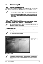
.... 1.8.2 Support DVD information The Support DVD that comes with the motherboard package contains the drivers, software applications, and utilities that you can install to the optical drive. Visit the ASUS website at any time without notice. Refer to your computer, browse...support 1.8.1 Installing an operating system This motherboard supports Windows® XP/Vista/7 Operating Systems (OS). Click an icon to display Support DVD/ motherboard information Click an item to locate the file ASSETUP.EXE from the BIN folder. The contents of your computer. ASUS P5G41-M LX2 Series 1-17
.... 1.8.2 Support DVD information The Support DVD that comes with the motherboard package contains the drivers, software applications, and utilities that you can install to the optical drive. Visit the ASUS website at any time without notice. Refer to your computer, browse...support 1.8.1 Installing an operating system This motherboard supports Windows® XP/Vista/7 Operating Systems (OS). Click an icon to display Support DVD/ motherboard information Click an item to locate the file ASSETUP.EXE from the BIN folder. The contents of your computer. ASUS P5G41-M LX2 Series 1-17
User Manual
Page 27
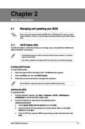
...to launch the ASUS Update utility. 2. Select Update BIOS from the Internet a. b. ASUS P5G41-M LX2 Series 2-1 From the Windows® desktop, click Start > Programs > ASUS > ASUSUpdate > ASUSUpdate to complete the installation. From the dropdown list, select any of the original motherboard BIOS file to... before you update the BIOS using the ASUS Update utility. 2.1.1 ASUS Update utility The ASUS Update is a utility that allows you to manage, save, and update the motherboard BIOS in Windows® environment. • ASUS Update requires an Internet connection either through ...
...to launch the ASUS Update utility. 2. Select Update BIOS from the Internet a. b. ASUS P5G41-M LX2 Series 2-1 From the Windows® desktop, click Start > Programs > ASUS > ASUSUpdate > ASUSUpdate to complete the installation. From the dropdown list, select any of the original motherboard BIOS file to... before you update the BIOS using the ASUS Update utility. 2.1.1 ASUS Update utility The ASUS Update is a utility that allows you to manage, save, and update the motherboard BIOS in Windows® environment. • ASUS Update requires an Internet connection either through ...

User Manual
Page 29
... power button to the optical drive or the removable device that contains the updated BIOS file. • The BIOS file in using the motherboard support DVD or a removable device that contains the BIOS file to the USB port or to restore the BIOS file when it fails or... do not press , POST continues with motherboard models. Recovering the BIOS To recover the BIOS: 1. Doing so can restore a corrupted BIOS file using the BIOS Setup program. Ensure to load the BIOS default settings to update the BIOS or configure its routines. ASUS P5G41-M LX2 Series 2-3 Refer to section 2.8 Exit ...
... power button to the optical drive or the removable device that contains the updated BIOS file. • The BIOS file in using the motherboard support DVD or a removable device that contains the BIOS file to the USB port or to restore the BIOS file when it fails or... do not press , POST continues with motherboard models. Recovering the BIOS To recover the BIOS: 1. Doing so can restore a corrupted BIOS file using the BIOS Setup program. Ensure to load the BIOS default settings to update the BIOS or configure its routines. ASUS P5G41-M LX2 Series 2-3 Refer to section 2.8 Exit ...

User Manual
Page 30
.... These values are for reference purposes only, and may not exactly match what you to your screen. • Visit the ASUS website at www.asus.com to ensure optimum performance. Change Field Tab Select Field F1 General Help F10 Save and Exit ESC Exit v02.61 (C)Copyright...items show Not Detected if no IDE/SATA device is a separate sub-menu for most conditions to download the latest BIOS file for this motherboard apply for each IDE/SATA device. Storage Configuration System Information Select Screen Select Item +- The BIOS automatically detects the values opposite the dimmed...
.... These values are for reference purposes only, and may not exactly match what you to your screen. • Visit the ASUS website at www.asus.com to ensure optimum performance. Change Field Tab Select Field F1 General Help F10 Save and Exit ESC Exit v02.61 (C)Copyright...items show Not Detected if no IDE/SATA device is a separate sub-menu for most conditions to download the latest BIOS file for this motherboard apply for each IDE/SATA device. Storage Configuration System Information Select Screen Select Item +- The BIOS automatically detects the values opposite the dimmed...

User Manual
Page 37
...ºF] or [Ignored] MB Temperature [xxxºC/xxxºF] or [Ignored] The onboard hardware monitor automatically detects and displays the motherboard and CPU temperatures. CPU/Chassis Fan Speed [xxxxRPM] or [Ignored] The onboard hardware monitor automatically detects and displays the CPU/chassis fan...] When set to [Power Off], the system goes into either off state after an AC power loss. Configuration options: [Disabled] [Enabled] ASUS P5G41-M LX2 Series 2-11 2.5.4 APM Configuration Restore on AC Power Loss [Power Off] When set to [Enabled], this item is not connected to display...
...ºF] or [Ignored] MB Temperature [xxxºC/xxxºF] or [Ignored] The onboard hardware monitor automatically detects and displays the motherboard and CPU temperatures. CPU/Chassis Fan Speed [xxxxRPM] or [Ignored] The onboard hardware monitor automatically detects and displays the CPU/chassis fan...] When set to [Power Off], the system goes into either off state after an AC power loss. Configuration options: [Disabled] [Enabled] ASUS P5G41-M LX2 Series 2-11 2.5.4 APM Configuration Restore on AC Power Loss [Power Off] When set to [Enabled], this item is not connected to display...


