

User Manual
Page 3
...(CPU 1-3 1.4 System memory 1-3 1.4.1 Overview 1-3 1.4.2 Memory configurations 1-4 1.5 Expansion slots 1-7 1.5.1 Installing an expansion card 1-7 1.5.2 Configuring an expansion card 1-7 1.5.3 PCI slots 1-7 1.5.4 PCI Express x1 slot 1-7 1.5.5 PCI Express x16 slot 1-7 1.6 Jumpers 1-8 1.7 Connectors 1-10 1.7.1 Rear panel ports 1-10 1.7.2 Internal connectors 1-11 1.8 Software support 1-17 1.8.1 Installing an operating system 1-17 1.8.2 Support DVD information 1-17 Chapter 2: BIOS information 2.1 Managing and updating your BIOS 2-1 2.1.1 ASUS Update utility 2-1 2.1.2 ASUS EZ Flash...
...(CPU 1-3 1.4 System memory 1-3 1.4.1 Overview 1-3 1.4.2 Memory configurations 1-4 1.5 Expansion slots 1-7 1.5.1 Installing an expansion card 1-7 1.5.2 Configuring an expansion card 1-7 1.5.3 PCI slots 1-7 1.5.4 PCI Express x1 slot 1-7 1.5.5 PCI Express x16 slot 1-7 1.6 Jumpers 1-8 1.7 Connectors 1-10 1.7.1 Rear panel ports 1-10 1.7.2 Internal connectors 1-11 1.8 Software support 1-17 1.8.1 Installing an operating system 1-17 1.8.2 Support DVD information 1-17 Chapter 2: BIOS information 2.1 Managing and updating your BIOS 2-1 2.1.1 ASUS Update utility 2-1 2.1.2 ASUS EZ Flash...
User Manual
Page 8
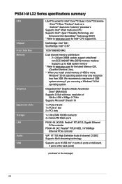
... Ethernet PCIe controller VIA® VT1705 High Definition Audio 6-channel CODEC Supports Multi-streaming technology Supports up to 8GB system memory * Refer to www.asus.com for the latest Memory QVL (Qualified Vendors Lists). ** When you are using a Windows® 32-bit operating system. resolution of 4GB or more, Windows® 32-bit operating system may only recognize less than 3GB. P5G41-M LX2 Series specifications summary CPU Chipset Front Side Bus Memory Graphics Expansion slots Storage LAN Audio USB LGA775 socket for...
... Ethernet PCIe controller VIA® VT1705 High Definition Audio 6-channel CODEC Supports Multi-streaming technology Supports up to 8GB system memory * Refer to www.asus.com for the latest Memory QVL (Qualified Vendors Lists). ** When you are using a Windows® 32-bit operating system. resolution of 4GB or more, Windows® 32-bit operating system may only recognize less than 3GB. P5G41-M LX2 Series specifications summary CPU Chipset Front Side Bus Memory Graphics Expansion slots Storage LAN Audio USB LGA775 socket for...
User Manual
Page 11
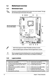
USB device wake-up (3-pin USBPW1-4, USBPW5-8) 5. LGA775 CPU socket 6. SATA connectors (7-pin SATA1-4) 1-11 9. Clear RTC RAM (3-pin CLRTC) 1-9 11. Place six screws into the chassis in the correct orientation. Doing so can damage the motherboard. 1.2.2 Layout contents Connectors/Jumpers/Slots/LED 1. DDR2 DIMM slots 7. DO NOT overtighten the screws! CPU and Chassis fan connectors (4-pin CPU_FAN and 3-pin CHA_FAN) 4. Optical drive audio connector (4-pin CD) 1-13 14. USB connectors (10-1 pin USB56, USB78) 1-3 12. Keyboard power (3-pin KBPWR) 2. Front panel audio connector (...
USB device wake-up (3-pin USBPW1-4, USBPW5-8) 5. LGA775 CPU socket 6. SATA connectors (7-pin SATA1-4) 1-11 9. Clear RTC RAM (3-pin CLRTC) 1-9 11. Place six screws into the chassis in the correct orientation. Doing so can damage the motherboard. 1.2.2 Layout contents Connectors/Jumpers/Slots/LED 1. DDR2 DIMM slots 7. DO NOT overtighten the screws! CPU and Chassis fan connectors (4-pin CPU_FAN and 3-pin CHA_FAN) 4. Optical drive audio connector (4-pin CD) 1-13 14. USB connectors (10-1 pin USB56, USB78) 1-3 12. Keyboard power (3-pin KBPWR) 2. Front panel audio connector (...
User Manual
Page 13
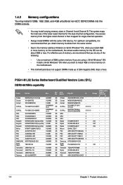
... For optimum compatibility, it is then mapped for the OS can be about 3GB or less. Use a maximum of 3GB system memory if you install 4GB or more memory on the motherboard, the actual usable memory for single-channel operation. • Always install DIMMs with the same CAS latency. P5G41-M LX2 Series Motherboard Qualified Vendors Lists (QVL) DDR2-667MHz capability Vendor Part No. CL Voltage A-Data...
... For optimum compatibility, it is then mapped for the OS can be about 3GB or less. Use a maximum of 3GB system memory if you install 4GB or more memory on the motherboard, the actual usable memory for single-channel operation. • Always install DIMMs with the same CAS latency. P5G41-M LX2 Series Motherboard Qualified Vendors Lists (QVL) DDR2-667MHz capability Vendor Part No. CL Voltage A-Data...
User Manual
Page 16
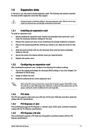
... necessary BIOS settings, if any. Otherwise, conflicts will arise between the two PCI groups, making the system unstable and the card inoperable. 1.5.3 PCI slots The PCI slot supports cards such as a LAN card, SCSI card, USB card, and other cards that comply with PCI specifications. 1.5.4 PCI Express x1 slot This motherboard supports PCI Express x1 network cards, SCSI cards, and other cards that comply with the PCI Express specifications. 1.5.5 PCI Express x16 slot This motherboard supports a PCI Express x16 graphics card that came with the PCI Express specifications. ASUS P5G41-M LX2 Series...
... necessary BIOS settings, if any. Otherwise, conflicts will arise between the two PCI groups, making the system unstable and the card inoperable. 1.5.3 PCI slots The PCI slot supports cards such as a LAN card, SCSI card, USB card, and other cards that comply with PCI specifications. 1.5.4 PCI Express x1 slot This motherboard supports PCI Express x1 network cards, SCSI cards, and other cards that comply with the PCI Express specifications. 1.5.5 PCI Express x16 slot This motherboard supports a PCI Express x16 graphics card that came with the PCI Express specifications. ASUS P5G41-M LX2 Series...
User Manual
Page 18
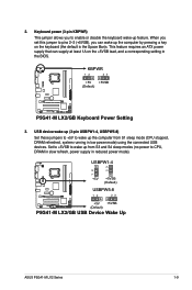
... S3 and S4 sleep modes (no power to CPU, DRAM in slow refresh, power supply in the BIOS. When you set this jumper to pins 2-3 (+5VSB), you to wake up from S1 sleep mode (CPU stopped, DRAM refreshed, system running in low power mode) using the connected USB devices. USBPW1-4 12 23 +5V +5VSB (Default) USBPW5-8 P5G41-M LX2/GB 12 23 +5V +5VSB (Default) P5G41-M LX2/GB USB Device Wake Up ASUS P5G41-M LX2 Series 1-9 KBPWR 12 23 +5V +5VSB (Default) P5G41-M LX2/GB P5G41-M LX2/GB Keyboard Power Setting 3. Keyboard power (3-pin KBPWR) This jumper allows you can supply at least...
... S3 and S4 sleep modes (no power to CPU, DRAM in slow refresh, power supply in the BIOS. When you set this jumper to pins 2-3 (+5VSB), you to wake up from S1 sleep mode (CPU stopped, DRAM refreshed, system running in low power mode) using the connected USB devices. USBPW1-4 12 23 +5V +5VSB (Default) USBPW5-8 P5G41-M LX2/GB 12 23 +5V +5VSB (Default) P5G41-M LX2/GB USB Device Wake Up ASUS P5G41-M LX2 Series 1-9 KBPWR 12 23 +5V +5VSB (Default) P5G41-M LX2/GB P5G41-M LX2/GB Keyboard Power Setting 3. Keyboard power (3-pin KBPWR) This jumper allows you can supply at least...
User Manual
Page 19
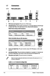
... connection LED LED (Orange) (Green) LAN port P5G41-M LX2/GB LAN port LED indications Activity/Link LED Status Description OFF No link ORANGE Linked BLINKING Data activity Speed LED Status OFF ORANGE GREEN Description 10Mbps connection 100Mbps connection 1Gbps connection ACT/LINK SPEED LED LED LAN port 3. This port connects a tape, CD, DVD player, or other audio sources. 4. Refer to a Local Area Network (LAN) through a network hub. This port allows connection to the audio configuration table below for a PS/2 mouse. 2. This port connects a headphone or a speaker...
... connection LED LED (Orange) (Green) LAN port P5G41-M LX2/GB LAN port LED indications Activity/Link LED Status Description OFF No link ORANGE Linked BLINKING Data activity Speed LED Status OFF ORANGE GREEN Description 10Mbps connection 100Mbps connection 1Gbps connection ACT/LINK SPEED LED LED LAN port 3. This port connects a tape, CD, DVD player, or other audio sources. 4. Refer to a Local Area Network (LAN) through a network hub. This port allows connection to the audio configuration table below for a PS/2 mouse. 2. This port connects a headphone or a speaker...
User Manual
Page 20
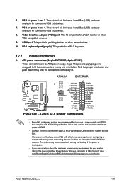
... not boot. • We recommend that you use a power supply unit (PSU) that you use a PSU with a higher power output when configuring a system with ATX 12V Specification 2.0 or later version and provides a minimum power of 400W. • DO NOT forget to the Recommended Power Supply Wattage Calculator at http://support.asus. This port is for a PS/2 keyboard. 1.7.2 Internal connectors 1. USB 2.0 ports 3 and 4. This 15-pin port is for a VGA monitor or other serial devices. 10. This port is...
... not boot. • We recommend that you use a power supply unit (PSU) that you use a PSU with a higher power output when configuring a system with ATX 12V Specification 2.0 or later version and provides a minimum power of 400W. • DO NOT forget to the Recommended Power Supply Wattage Calculator at http://support.asus. This port is for a PS/2 keyboard. 1.7.2 Internal connectors 1. USB 2.0 ports 3 and 4. This 15-pin port is for a VGA monitor or other serial devices. 10. This port is...
User Manual
Page 21
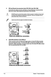
.../s hard disk drives and optical disk drives. Only the 4-pin CPU fan supports the ASUS Q-Fan feature. DO NOT forget to connect the fan cables to the fan connectors on the fan connectors! Do not place jumper caps on the motherboard, ensuring that the black wire of each cable matches the ground pin of the Serial ATA 3Gb/s is backward compatible with the Serial ATA 1.5Gb/s specification. P5G41-M LX2/GB CHA_FAN Rotation +12V GND CPU_FAN CPU FAN PWM CPU FAN IN CPU FAN PWR GND P5G41-M LX2/GB fan connectors 3. The...
.../s hard disk drives and optical disk drives. Only the 4-pin CPU fan supports the ASUS Q-Fan feature. DO NOT forget to connect the fan cables to the fan connectors on the fan connectors! Do not place jumper caps on the motherboard, ensuring that the black wire of each cable matches the ground pin of the Serial ATA 3Gb/s is backward compatible with the Serial ATA 1.5Gb/s specification. P5G41-M LX2/GB CHA_FAN Rotation +12V GND CPU_FAN CPU FAN PWM CPU FAN IN CPU FAN PWR GND P5G41-M LX2/GB fan connectors 3. The...
User Manual
Page 26
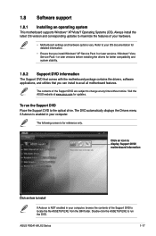
... your computer, browse the contents of the Support DVD are subject to change at www.asus.com for better compatibility and system stability. 1.8.2 Support DVD information The Support DVD that comes with the motherboard package contains the drivers, software applications, and utilities that you can install to locate the file ASSETUP.EXE from the BIN folder. The following screen is enabled in your hardware. • Motherboard settings and hardware options vary.
... your computer, browse the contents of the Support DVD are subject to change at www.asus.com for better compatibility and system stability. 1.8.2 Support DVD information The Support DVD that comes with the motherboard package contains the drivers, software applications, and utilities that you can install to locate the file ASSETUP.EXE from the BIN folder. The following screen is enabled in your hardware. • Motherboard settings and hardware options vary.
User Manual
Page 27
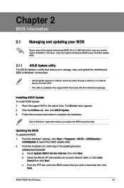
... drive. Updating the BIOS To update the BIOS: 1. From the Windows® desktop, click Start > Programs > ASUS > ASUSUpdate > ASUSUpdate to complete the installation. From the dropdown list, select any of the original motherboard BIOS file to a USB flash disk in case you to restore the BIOS in the future. The Drivers menu appears. 2. Select the ASUS FTP site nearest you wish to avoid network traffic, or click Auto Select then click Next. b. ASUS P5G41-M LX2 Series 2-1 Place the support DVD...
... drive. Updating the BIOS To update the BIOS: 1. From the Windows® desktop, click Start > Programs > ASUS > ASUSUpdate > ASUSUpdate to complete the installation. From the dropdown list, select any of the original motherboard BIOS file to a USB flash disk in case you to restore the BIOS in the future. The Drivers menu appears. 2. Select the ASUS FTP site nearest you wish to avoid network traffic, or click Auto Select then click Next. b. ASUS P5G41-M LX2 Series 2-1 Place the support DVD...
User Manual
Page 28
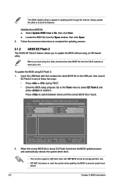
... boot failure! 2-2 Chapter 2: BIOS information Before you to complete the updating process. 2.1.2 ASUS EZ Flash 2 The ASUS EZ Flash 2 feature allows you start using EZ Flash 2: 1. When the correct BIOS file is found . Updating from the Open window, then click Open. 3. ASUSTek EZ Flash 2 BIOS ROM Utility V3.44 FLASH TYPE: MXIC 25L8005 Current ROM BOARD: P5G41-M LX2/GB VER: 0211 (H:00 B:03) DATE: 09/28/2009 Update ROM BOARD: Unknown VER: Unknown DATE: Unknown PATH: A:\ A: Note [Enter] Select or Load...
... boot failure! 2-2 Chapter 2: BIOS information Before you to complete the updating process. 2.1.2 ASUS EZ Flash 2 The ASUS EZ Flash 2 feature allows you start using EZ Flash 2: 1. When the correct BIOS file is found . Updating from the Open window, then click Open. 3. ASUSTek EZ Flash 2 BIOS ROM Utility V3.44 FLASH TYPE: MXIC 25L8005 Current ROM BOARD: P5G41-M LX2/GB VER: 0211 (H:00 B:03) DATE: 09/28/2009 Update ROM BOARD: Unknown VER: Unknown DATE: Unknown PATH: A:\ A: Note [Enter] Select or Load...

User Manual
Page 29
.... For motherboards without the floppy connector, prepare a USB flash disk before using the motherboard support DVD or a removable device that contains the BIOS file to the USB port or to turn on the system chassis. • Press the power button to the floppy disk drive, if supported. 3. When found, the utility reads the BIOS file and starts flashing the corrupted BIOS file. 4. Ensure to load the BIOS default settings to enter BIOS Setup using the BIOS Setup program. Entering BIOS Setup after POST To enter BIOS Setup after the utility completes the updating process and turn the...
.... For motherboards without the floppy connector, prepare a USB flash disk before using the motherboard support DVD or a removable device that contains the BIOS file to the USB port or to turn on the system chassis. • Press the power button to the floppy disk drive, if supported. 3. When found, the utility reads the BIOS file and starts flashing the corrupted BIOS file. 4. Ensure to load the BIOS default settings to enter BIOS Setup using the BIOS Setup program. Entering BIOS Setup after POST To enter BIOS Setup after the utility completes the updating process and turn the...

User Manual
Page 30
....asus.com to download the latest BIOS file for this motherboard. 2.3 Main menu When you enter the BIOS Setup program, the Main menu screen appears, giving you to set the system date. 2.3.3 Primary IDE Master/Slave, SATA1~4 While entering Setup, the BIOS automatically detects the presence of the basic system information. These items show Not Detected if no IDE/SATA device is a separate sub-menu for each IDE/SATA device. Using the power button, reset button, or the ++ keys to force reset...
....asus.com to download the latest BIOS file for this motherboard. 2.3 Main menu When you enter the BIOS Setup program, the Main menu screen appears, giving you to set the system date. 2.3.3 Primary IDE Master/Slave, SATA1~4 While entering Setup, the BIOS automatically detects the presence of the basic system information. These items show Not Detected if no IDE/SATA device is a separate sub-menu for each IDE/SATA device. Using the power button, reset button, or the ++ keys to force reset...

User Manual
Page 31
... Smart Monitoring, Analysis, and Reporting Technology. Select an item then press if you to Auto allows automatic selection of IDE drive. Configuration options: [Disabled] [Compatible] [Enhanced] Enhanced Mode Support On [S-ATA] Sets Serial ATA, Parallel ATA or both as native mode. Configuration options: [Auto] [0] [1] [2] [3] [4] DMA Mode [Auto] Selects the DMA mode. Configuration options: [Auto] [Disabled] [Enabled] 32Bit Data Transfer [Enabled] Enables or disables 32-bit data transfer. Configuration options: [0] [5] [10] [15] [20] [25] [30] [35] ASUS P5G41-M LX2 Series...
... Smart Monitoring, Analysis, and Reporting Technology. Select an item then press if you to Auto allows automatic selection of IDE drive. Configuration options: [Disabled] [Compatible] [Enhanced] Enhanced Mode Support On [S-ATA] Sets Serial ATA, Parallel ATA or both as native mode. Configuration options: [Auto] [0] [1] [2] [3] [4] DMA Mode [Auto] Selects the DMA mode. Configuration options: [Auto] [Disabled] [Enabled] 32Bit Data Transfer [Enabled] Enables or disables 32-bit data transfer. Configuration options: [0] [5] [10] [15] [20] [25] [30] [35] ASUS P5G41-M LX2 Series...
User Manual
Page 34
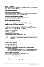
... DIMM sockets. If High Definition Audio Front Panel used by SPD. Configuration options: [Enabled] [Disabled] Onboard LAN Boot ROM [Disabled] Allows you to select the front panel support type. 2.4.2 Chipset The Chipset menu allows you to select the amout of overlapped PCI memory above the total physical memory. Select an item then press to change the advanced chipset settings. Configuration options: [IGD] [PCI/IGD] [PCI/PEG] [PEG/IGD] [PEG/PCI] IGD Graphics Mode Select [Enabled, 32MB] Allows you to display the sub-menu. Protect Audio Video Path Mode [Lite...
... DIMM sockets. If High Definition Audio Front Panel used by SPD. Configuration options: [Enabled] [Disabled] Onboard LAN Boot ROM [Disabled] Allows you to select the front panel support type. 2.4.2 Chipset The Chipset menu allows you to select the amout of overlapped PCI memory above the total physical memory. Select an item then press to change the advanced chipset settings. Configuration options: [IGD] [PCI/IGD] [PCI/PEG] [PEG/IGD] [PEG/PCI] IGD Graphics Mode Select [Enabled, 32MB] Allows you to display the sub-menu. Protect Audio Video Path Mode [Lite...
User Manual
Page 35
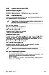
... devices at startup. Setting to [Auto] allows the system to enable or disable USB 2.0 controller. If detected, the USB controller legacy mode is plugged. 2.4.3 Onboard Devices Configuration Serial Port1 Address [3F8/IRQ4] Allows you to select the emulation type. Configuration options: [Enabled] [Disabled] Legacy USB Support [Auto] Allows you to enable or disable support for the USB storage device to set the maximum time that the BIOS waits for Legacy USB storage devices, including USB flash drives and USB hard drives. USB Mass Storage Device Configuration USB Mass Storage Reset...
... devices at startup. Setting to [Auto] allows the system to enable or disable USB 2.0 controller. If detected, the USB controller legacy mode is plugged. 2.4.3 Onboard Devices Configuration Serial Port1 Address [3F8/IRQ4] Allows you to select the emulation type. Configuration options: [Enabled] [Disabled] Legacy USB Support [Auto] Allows you to enable or disable support for the USB storage device to set the maximum time that the BIOS waits for Legacy USB storage devices, including USB flash drives and USB hard drives. USB Mass Storage Device Configuration USB Mass Storage Reset...

User Manual
Page 36
... the PCI PnP menu items. Incorrect field values can cause the system to display the configuration options. Main Advanced Power BIOS SETUP UTILITY Boot Tools Exit Suspend Mode [Auto] ACPI 2.0 Support [Enabled] ACPI APIC Support [Enabled] APM Configuration Hardware Monitor Select the ACPI state used for System Suspend. 2.5.1 Suspend Mode [Auto] Allows you to enable or disable the Advanced Configuration and Power Interface (ACPI) support in the Application-Specific Integrated Circuit (ASIC). When set to [No], BIOS configures all the devices in the RSDT pointer list. Plug and...
... the PCI PnP menu items. Incorrect field values can cause the system to display the configuration options. Main Advanced Power BIOS SETUP UTILITY Boot Tools Exit Suspend Mode [Auto] ACPI 2.0 Support [Enabled] ACPI APIC Support [Enabled] APM Configuration Hardware Monitor Select the ACPI state used for System Suspend. 2.5.1 Suspend Mode [Auto] Allows you to enable or disable the Advanced Configuration and Power Interface (ACPI) support in the Application-Specific Integrated Circuit (ASIC). When set to [No], BIOS configures all the devices in the RSDT pointer list. Plug and...

User Manual
Page 37
... you to enable or disable RTC to generate a wake event. VCORE Voltage, 3.3V Voltage, 5V Voltage, 12V Voltage [xxxV] or [Ignored] The onboard hardware monitor automatically detects the voltage output through a PCI/PCIe device. Configuration options: [Disabled] [Enabled] ASUS P5G41-M LX2 Series 2-11 Configuration options: [Disabled] [Enabled] Power On by PCI(E) Device [Disabled] When set values. Configuration options: [Disabled] [Enabled] Power On By PS/2 Keyboard [Disabled] Allows you to the motherboard, the field shows N/A. This feature requires an ATX power supply that...
... you to enable or disable RTC to generate a wake event. VCORE Voltage, 3.3V Voltage, 5V Voltage, 12V Voltage [xxxV] or [Ignored] The onboard hardware monitor automatically detects the voltage output through a PCI/PCIe device. Configuration options: [Disabled] [Enabled] ASUS P5G41-M LX2 Series 2-11 Configuration options: [Disabled] [Enabled] Power On by PCI(E) Device [Disabled] When set values. Configuration options: [Disabled] [Enabled] Power On By PS/2 Keyboard [Disabled] Allows you to the motherboard, the field shows N/A. This feature requires an ATX power supply that...

User Manual
Page 38
... of devices installed in Safe Mode, do any of the following: • Press when ASUS Logo appears. • Press after POST. 2.6.2 Boot Settings Configuration Quick Boot [Enabled] Enabling this item to [Enabled] to use the ASUS MyLogo2™ feature. A virtual floppy disk drive (Floppy Drive B: ) may appear when you to select the power-on self tests (POST) while booting to decrease the time needed to boot the system. Configuration options: [Removable Dev.] [Hard Drive] [ATAPI CD-ROM] [Disabled] • To select the boot device...
... of devices installed in Safe Mode, do any of the following: • Press when ASUS Logo appears. • Press after POST. 2.6.2 Boot Settings Configuration Quick Boot [Enabled] Enabling this item to [Enabled] to use the ASUS MyLogo2™ feature. A virtual floppy disk drive (Floppy Drive B: ) may appear when you to select the power-on self tests (POST) while booting to decrease the time needed to boot the system. Configuration options: [Removable Dev.] [Hard Drive] [ATAPI CD-ROM] [Disabled] • To select the boot device...


