

User Manual
Page 1
Motherboard P5G41-M LX2 Series • P5G41-M LX2 • P5G41-M LX2/GB
Motherboard P5G41-M LX2 Series • P5G41-M LX2 • P5G41-M LX2/GB

User Manual
Page 3
Contents Notices...v Safety information vi About this guide vi P5G41-M LX2 Series specifications summary viii Chapter 1: Product introduction 1.1 Before you proceed 1-1 1.2 Motherboard overview 1-2 1.2.1 Motherboard layout 1-2 1.2.2 Layout contents 1-2 1.3 Central Processing Unit (CPU 1-3 1.4 System memory 1-3 1.4.1 Overview 1-3 1.4.2 Memory configurations 1-4 1.5 Expansion ... DVD information 1-17 Chapter 2: BIOS information 2.1 Managing and updating your BIOS 2-1 2.1.1 ASUS Update utility 2-1 2.1.2 ASUS EZ Flash 2 2-2 2.1.3 ASUS CrashFree BIOS 2-3 2.2 BIOS setup program 2-3 iii
Contents Notices...v Safety information vi About this guide vi P5G41-M LX2 Series specifications summary viii Chapter 1: Product introduction 1.1 Before you proceed 1-1 1.2 Motherboard overview 1-2 1.2.1 Motherboard layout 1-2 1.2.2 Layout contents 1-2 1.3 Central Processing Unit (CPU 1-3 1.4 System memory 1-3 1.4.1 Overview 1-3 1.4.2 Memory configurations 1-4 1.5 Expansion ... DVD information 1-17 Chapter 2: BIOS information 2.1 Managing and updating your BIOS 2-1 2.1.1 ASUS Update utility 2-1 2.1.2 ASUS EZ Flash 2 2-2 2.1.3 ASUS CrashFree BIOS 2-3 2.2 BIOS setup program 2-3 iii
User Manual
Page 5
...could void the user's authority to operate this equipment. REACH Complying with manufacturer's instructions, may cause undesired operation. DO NOT throw the motherboard in municipal waste. However, there is subject to the following measures: • Reorient or relocate the receiving antenna. • Increase the...and found to enable proper reuse of Chemicals) regulatory framework, we published the chemical substances in our products at ASUS REACH website at http://green.asus.com/english/REACH.htm. These limits are designed to which can radiate radio frequency energy and, if not ...
...could void the user's authority to operate this equipment. REACH Complying with manufacturer's instructions, may cause undesired operation. DO NOT throw the motherboard in municipal waste. However, there is subject to the following measures: • Reorient or relocate the receiving antenna. • Increase the...and found to enable proper reuse of Chemicals) regulatory framework, we published the chemical substances in our products at ASUS REACH website at http://green.asus.com/english/REACH.htm. These limits are designed to which can radiate radio frequency energy and, if not ...

User Manual
Page 6
...fix it may become wet. • Place the product on a stable surface. • If you need when installing and configuring the motherboard. About this guide is broken, do not try to change system settings through the BIOS Setup menus. Contact a qualified service technician or... the power supply is organized This guide contains the following parts: • Chapter 1: Product introduction This chapter describes the features of the motherboard and the new technology it , carefully read all power cables are unplugged. • Seek professional assistance before the signal cables are also...
...fix it may become wet. • Place the product on a stable surface. • If you need when installing and configuring the motherboard. About this guide is broken, do not try to change system settings through the BIOS Setup menus. Contact a qualified service technician or... the power supply is organized This guide contains the following parts: • Chapter 1: Product introduction This chapter describes the features of the motherboard and the new technology it , carefully read all power cables are unplugged. • Seek professional assistance before the signal cables are also...
User Manual
Page 10
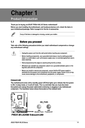
Refer to page ix for buying an ASUS® P5G41-M LX2 Series motherboard! The illustration below shows the location of the items is damaged or missing, contact your motherboard package. Before you start installing the motherboard, and hardware devices on a grounded antistatic pad or ...to do so may cause severe damage to the motherboard, peripherals, or components. This is a reminder that you for the list of accessories. SB_PWR P5G41-M LX2/GB ON OFF Standby Power Powered Off P5G41-M LX2/GB Onboard LED ASUS P5G41-M LX2 Series 1-1 Chapter 1 Product introduction Thank you must...
Refer to page ix for buying an ASUS® P5G41-M LX2 Series motherboard! The illustration below shows the location of the items is damaged or missing, contact your motherboard package. Before you start installing the motherboard, and hardware devices on a grounded antistatic pad or ...to do so may cause severe damage to the motherboard, peripherals, or components. This is a reminder that you for the list of accessories. SB_PWR P5G41-M LX2/GB ON OFF Standby Power Powered Off P5G41-M LX2/GB Onboard LED ASUS P5G41-M LX2 Series 1-1 Chapter 1 Product introduction Thank you must...
User Manual
Page 11
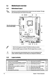
...SATA4 SATA3 SATA2 SATA1 8Mb BIOS PCI2 8 SB_PWR USBPW5-8 USB56 USB78 CLRTC F_PANEL 14 13 4 12 11 10 9 • P5G41-M LX2 integrates the Realtek® RTL8103EL Fast Ethernet controller. • P5G41-M LX2/GB integrates the Realtek® RTL8112L Gigabit Ethernet controller. Keyboard power (3-pin KBPWR) 2. CPU and Chassis fan connectors (4-pin CPU_FAN and...connector (4-pin CD) 1-13 14. DO NOT overtighten the screws! USB device wake-up (3-pin USBPW1-4, USBPW5-8) 5. Doing so can damage the motherboard. 1.2.2 Layout contents Connectors/Jumpers/Slots/LED 1. LGA775 CPU socket 6.
...SATA4 SATA3 SATA2 SATA1 8Mb BIOS PCI2 8 SB_PWR USBPW5-8 USB56 USB78 CLRTC F_PANEL 14 13 4 12 11 10 9 • P5G41-M LX2 integrates the Realtek® RTL8103EL Fast Ethernet controller. • P5G41-M LX2/GB integrates the Realtek® RTL8112L Gigabit Ethernet controller. Keyboard power (3-pin KBPWR) 2. CPU and Chassis fan connectors (4-pin CPU_FAN and...connector (4-pin CD) 1-13 14. DO NOT overtighten the screws! USB device wake-up (3-pin USBPW1-4, USBPW5-8) 5. Doing so can damage the motherboard. 1.2.2 Layout contents Connectors/Jumpers/Slots/LED 1. LGA775 CPU socket 6.
User Manual
Page 12
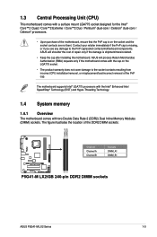
...motherboard comes with a surface mount LGA775 socket designed for the Intel® Core™2 Quad / Core™2 Extreme / Core™2 Duo / Pentium® dual-core / Celeron® dual-core / Celeron® processors. • Upon purchase of the DDR2 DIMM sockets: DIMM_A1 DIMM_B1 P5G41-M LX2/GB Channel Channel A Channel B Sockets DIMM_A1 DIMM_B1 P5G41-M LX2/GB... 240-pin DDR2 DIMM sockets ASUS P5G41-M LX2 Series 1-3 Contact your retailer immediately if ...
...motherboard comes with a surface mount LGA775 socket designed for the Intel® Core™2 Quad / Core™2 Extreme / Core™2 Duo / Pentium® dual-core / Celeron® dual-core / Celeron® processors. • Upon purchase of the DDR2 DIMM sockets: DIMM_A1 DIMM_B1 P5G41-M LX2/GB Channel Channel A Channel B Sockets DIMM_A1 DIMM_B1 P5G41-M LX2/GB... 240-pin DDR2 DIMM sockets ASUS P5G41-M LX2 Series 1-3 Contact your retailer immediately if ...
User Manual
Page 13
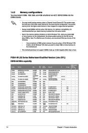
P5G41-M LX2 Series Motherboard Qualified Vendors Lists (QVL) DDR2-667MHz capability Vendor Part No. Corsair MID095D62864M8CEC - - Corsair MIII0052532M8CEC - - Samsung K4T2G084QA-HCE6 - - For optimum compatibility, it is then mapped for ... Talent PG 64M8-800 0750 5 1.8V Transced TQ243PCF8T0838 5 - Any excess memory from the same vendor. • Due to install 4GB or more memory on the motherboard. • This motherboard does not support DIMMs made up of 3GB system memory if you install 4GB or more memory on the...
P5G41-M LX2 Series Motherboard Qualified Vendors Lists (QVL) DDR2-667MHz capability Vendor Part No. Corsair MID095D62864M8CEC - - Corsair MIII0052532M8CEC - - Samsung K4T2G084QA-HCE6 - - For optimum compatibility, it is then mapped for ... Talent PG 64M8-800 0750 5 1.8V Transced TQ243PCF8T0838 5 - Any excess memory from the same vendor. • Due to install 4GB or more memory on the motherboard. • This motherboard does not support DIMMs made up of 3GB system memory if you install 4GB or more memory on the...
User Manual
Page 16
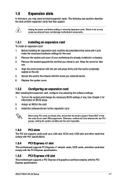
... comply with PCI specifications. 1.5.4 PCI Express x1 slot This motherboard supports PCI Express x1 network cards, SCSI cards, and other cards that comply with the screw you intend to install expansion cards. ASUS P5G41-M LX2 Series 1-7 1.5 Expansion slots In the future, you physical ...injury and damage motherboard components. 1.5.1 Installing an expansion card To install an expansion card: 1. Keep the screw for...
... comply with PCI specifications. 1.5.4 PCI Express x1 slot This motherboard supports PCI Express x1 network cards, SCSI cards, and other cards that comply with the screw you intend to install expansion cards. ASUS P5G41-M LX2 Series 1-7 1.5 Expansion slots In the future, you physical ...injury and damage motherboard components. 1.5.1 Installing an expansion card To install an expansion card: 1. Keep the screw for...
User Manual
Page 21
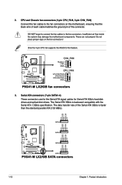
...motherboard, ensuring that the black wire of each cable matches the ground pin of the Serial ATA 3Gb/s is backward compatible with the Serial ATA 1.5Gb/s specification. These are for the Serial ATA signal cables for Serial ATA 3Gb/s hard disk drives and optical disk drives. P5G41-M LX2/GB... GND RSATA_RXN2 RSATA_RXP2 GND RSATA_TXN2 RSATA_TXP2 GND GND RSATA_RXN1 RSATA_RXP1 GND RSATA_TXN1 RSATA_TXP1 GND P5G41-M LX2/GB SATA2 SATA1 P5G41-M LX2/GB SATA connectors 1-12 Chapter 1: Product introduction CPU and Chassis fan connectors (4-pin ... 4-pin CPU fan supports the ASUS Q-Fan feature.
...motherboard, ensuring that the black wire of each cable matches the ground pin of the Serial ATA 3Gb/s is backward compatible with the Serial ATA 1.5Gb/s specification. These are for the Serial ATA signal cables for Serial ATA 3Gb/s hard disk drives and optical disk drives. P5G41-M LX2/GB... GND RSATA_RXN2 RSATA_RXP2 GND RSATA_TXN2 RSATA_TXP2 GND GND RSATA_RXN1 RSATA_RXP1 GND RSATA_TXN1 RSATA_TXP1 GND P5G41-M LX2/GB SATA2 SATA1 P5G41-M LX2/GB SATA connectors 1-12 Chapter 1: Product introduction CPU and Chassis fan connectors (4-pin ... 4-pin CPU fan supports the ASUS Q-Fan feature.
User Manual
Page 22
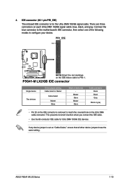
...P5G41-M LX2/GB NOTE:Orient the red markings on the Ultra DMA cable connector. This prevents incorrect insertion when you connect the IDE cable. • Use the 80-conductor IDE cable for the Ultra DMA 100/66 signal cable. Connect the blue connector to the motherboard's IDE connector, then select one of device(s) - ASUS P5G41-M LX2...IDE devices. There are three connectors on each Ultra DMA 100/66 signal cable: blue, black, and gray. P5G41-M LX2/GB IDE connector Single device Two devices Drive jumper setting Cable-Select or Master Cable-Select Master Slave Mode of the following ...
...P5G41-M LX2/GB NOTE:Orient the red markings on the Ultra DMA cable connector. This prevents incorrect insertion when you connect the IDE cable. • Use the 80-conductor IDE cable for the Ultra DMA 100/66 signal cable. Connect the blue connector to the motherboard's IDE connector, then select one of device(s) - ASUS P5G41-M LX2...IDE devices. There are three connectors on each Ultra DMA 100/66 signal cable: blue, black, and gray. P5G41-M LX2/GB IDE connector Single device Two devices Drive jumper setting Cable-Select or Master Cable-Select Master Slave Mode of the following ...
User Manual
Page 23
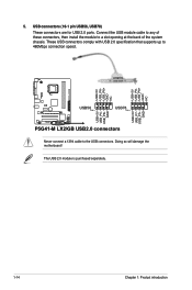
... NC USB+5V USB_P6USB_P6+ GND NC P5G41-M LX2/GB USB56 PIN 1 USB78 PIN 1 USB+5V USB_P7USB_P7+ GND USB+5V USB_P5USB_P5+ GND P5G41-M LX2/GB USB2.0 connectors Never connect a 1394 cable to the USB connectors. USB connectors (10-1 pin USB56, USB78) These connectors are for USB 2.0 ports. Doing so will damage the motherboard! The USB 2.0 module is purchased...
... NC USB+5V USB_P6USB_P6+ GND NC P5G41-M LX2/GB USB56 PIN 1 USB78 PIN 1 USB+5V USB_P7USB_P7+ GND USB+5V USB_P5USB_P5+ GND P5G41-M LX2/GB USB2.0 connectors Never connect a 1394 cable to the USB connectors. USB connectors (10-1 pin USB56, USB78) These connectors are for USB 2.0 ports. Doing so will damage the motherboard! The USB 2.0 module is purchased...
User Manual
Page 24
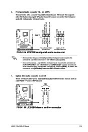
...-1 pin AAFP) This connector is set the item to this connector. CD Right Audio Channel GND GND Left Audio Channel P5G41-M LX2/GB P5G41-M LX2/GB Internal audio connector ASUS P5G41-M LX2 Series 1-15 Connect one end of the motherboard's high-definition audio capability. • If you want to connect a high-definition front panel audio module to this connector is...
...-1 pin AAFP) This connector is set the item to this connector. CD Right Audio Channel GND GND Left Audio Channel P5G41-M LX2/GB P5G41-M LX2/GB Internal audio connector ASUS P5G41-M LX2 Series 1-15 Connect one end of the motherboard's high-definition audio capability. • If you want to connect a high-definition front panel audio module to this connector is...
User Manual
Page 26
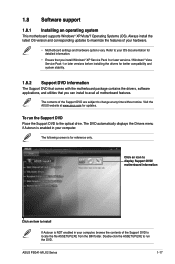
...later versions before installing the drivers for better compatibility and system stability. 1.8.2 Support DVD information The Support DVD that comes with the motherboard package contains the drivers, software applications, and utilities that you can install to locate the file ASSETUP.EXE from the BIN folder..... The DVD automatically displays the Drivers menu if Autorun is enabled in your hardware. • Motherboard settings and hardware options vary. ASUS P5G41-M LX2 Series 1-17 Always install the latest OS version and corresponding updates to maximize the features of your computer,...
...later versions before installing the drivers for better compatibility and system stability. 1.8.2 Support DVD information The Support DVD that comes with the motherboard package contains the drivers, software applications, and utilities that you can install to locate the file ASSETUP.EXE from the BIN folder..... The DVD automatically displays the Drivers menu if Autorun is enabled in your hardware. • Motherboard settings and hardware options vary. ASUS P5G41-M LX2 Series 1-17 Always install the latest OS version and corresponding updates to maximize the features of your computer,...
User Manual
Page 27
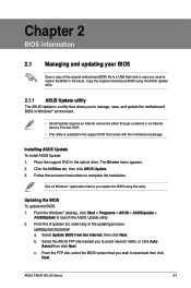
... wish to restore the BIOS in the future. Installing ASUS Update To install ASUS Update: 1. From the Windows® desktop, click Start > Programs > ASUS > ASUSUpdate > ASUSUpdate to complete the installation. ASUS P5G41-M LX2 Series 2-1 Copy the original motherboard BIOS using this utility. Follow the onscreen instructions to launch the ASUS Update utility. 2. Quit all Windows® applications before...
... wish to restore the BIOS in the future. Installing ASUS Update To install ASUS Update: 1. From the Windows® desktop, click Start > Programs > ASUS > ASUSUpdate > ASUSUpdate to complete the installation. ASUS P5G41-M LX2 Series 2-1 Copy the original motherboard BIOS using this utility. Follow the onscreen instructions to launch the ASUS Update utility. 2. Quit all Windows® applications before...

User Manual
Page 29
...; Press the reset button on the system chassis. • Press the power button to guide you do not press , POST continues with motherboard models. The utility automatically checks the devices for details. 2.2 BIOS setup program Use the BIOS Setup program to restore the BIOS file when ... BIOS Setup program. Entering BIOS Setup at startup To enter BIOS Setup at www.asus.com. • The removable devices that allows you failed to section 2.8 Exit menu for the BIOS file. ASUS P5G41-M LX2 Series 2-3 You can cause system boot failure! Recovering the BIOS To recover the BIOS...
...; Press the reset button on the system chassis. • Press the power button to guide you do not press , POST continues with motherboard models. The utility automatically checks the devices for details. 2.2 BIOS setup program Use the BIOS Setup program to restore the BIOS file when ... BIOS Setup program. Entering BIOS Setup at startup To enter BIOS Setup at www.asus.com. • The removable devices that allows you failed to section 2.8 Exit menu for the BIOS file. ASUS P5G41-M LX2 Series 2-3 You can cause system boot failure! Recovering the BIOS To recover the BIOS...

User Manual
Page 30
...information. Using the power button, reset button, or the ++ keys to force reset from the operating system. • The default BIOS settings for this motherboard. 2.3 Main menu When you enter the BIOS Setup program, the Main menu screen appears, giving you to set the system time. 2.3.2 System Date ...down the system properly from a running operating system can cause damage to your screen. • Visit the ASUS website at www.asus.com to download the latest BIOS file for this motherboard apply for each IDE/SATA device. Select the Load Setups Default item under the Exit Menu. There is...
...information. Using the power button, reset button, or the ++ keys to force reset from the operating system. • The default BIOS settings for this motherboard. 2.3 Main menu When you enter the BIOS Setup program, the Main menu screen appears, giving you to set the system time. 2.3.2 System Date ...down the system properly from a running operating system can cause damage to your screen. • Visit the ASUS website at www.asus.com to download the latest BIOS file for this motherboard apply for each IDE/SATA device. Select the Load Setups Default item under the Exit Menu. There is...

User Manual
Page 37
...xxxºF] or [Ignored] MB Temperature [xxxºC/xxxºF] or [Ignored] The onboard hardware monitor automatically detects and displays the motherboard and CPU temperatures. Configuration options: [Disabled] [Space Bar] [Power Key] [Ctrl-Esc] Power On By PS/2 Mouse [Disabled] ... or [Ignored] The onboard hardware monitor automatically detects the voltage output through a PCI/PCIe device. Configuration options: [Disabled] [Enabled] ASUS P5G41-M LX2 Series 2-11 When this parameter allows you to enable or disable RTC to generate a wake event. When set to [Power Off], ...
...xxxºF] or [Ignored] MB Temperature [xxxºC/xxxºF] or [Ignored] The onboard hardware monitor automatically detects and displays the motherboard and CPU temperatures. Configuration options: [Disabled] [Space Bar] [Power Key] [Ctrl-Esc] Power On By PS/2 Mouse [Disabled] ... or [Ignored] The onboard hardware monitor automatically detects the voltage output through a PCI/PCIe device. Configuration options: [Disabled] [Enabled] ASUS P5G41-M LX2 Series 2-11 When this parameter allows you to enable or disable RTC to generate a wake event. When set to [Power Off], ...


