
User Manual
Page 8
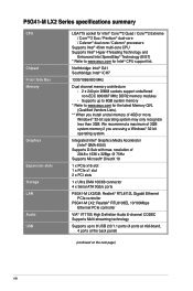
... 100/66 connector 4 x Serial ATA 3Gb/s ports P5G41-M LX2/GB: Realtek® RTL8112L Gigabit Ethernet PCIe controller P5G41-M LX2: Realtek® RTL8103EL 10/100Mbps Ethernet PCIe controller VIA® VT1705 High Definition Audio 6-channel CODEC Supports Multi-streaming technology Supports up to 8GB system memory * Refer to www.asus.com for the latest Memory QVL (Qualified...
... 100/66 connector 4 x Serial ATA 3Gb/s ports P5G41-M LX2/GB: Realtek® RTL8112L Gigabit Ethernet PCIe controller P5G41-M LX2: Realtek® RTL8103EL 10/100Mbps Ethernet PCIe controller VIA® VT1705 High Definition Audio 6-channel CODEC Supports Multi-streaming technology Supports up to 8GB system memory * Refer to www.asus.com for the latest Memory QVL (Qualified...
User Manual
Page 10
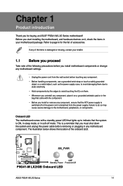
... before you install motherboard components or change any component, ensure that lights up to page ix for buying an ASUS® P5G41-M LX2 Series motherboard! SB_PWR P5G41-M LX2/GB ON OFF Standby Power Powered Off P5G41-M LX2/GB Onboard LED ASUS P5G41-M LX2 Series 1-1 Before you start installing the motherboard, and hardware devices on a grounded antistatic pad or in soft-off or...
... before you install motherboard components or change any component, ensure that lights up to page ix for buying an ASUS® P5G41-M LX2 Series motherboard! SB_PWR P5G41-M LX2/GB ON OFF Standby Power Powered Off P5G41-M LX2/GB Onboard LED ASUS P5G41-M LX2 Series 1-1 Before you start installing the motherboard, and hardware devices on a grounded antistatic pad or in soft-off or...
User Manual
Page 12
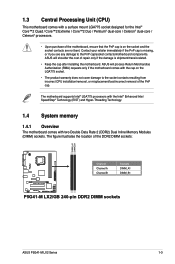
... System memory 1.4.1 Overview The motherboard comes with two Double Data Rate 2 (DDR2) Dual Inline Memory Modules (DIMM) sockets. ASUS will shoulder the cost of repair only if the damage is shipment/transit-related. • Keep the cap after installing the motherboard...are not bent. The figure illustrates the location of the DDR2 DIMM sockets: DIMM_A1 DIMM_B1 P5G41-M LX2/GB Channel Channel A Channel B Sockets DIMM_A1 DIMM_B1 P5G41-M LX2/GB 240-pin DDR2 DIMM sockets ASUS P5G41-M LX2 Series 1-3 1.3 Central Processing Unit (CPU) This motherboard comes with a surface mount LGA775...
... System memory 1.4.1 Overview The motherboard comes with two Double Data Rate 2 (DDR2) Dual Inline Memory Modules (DIMM) sockets. ASUS will shoulder the cost of repair only if the damage is shipment/transit-related. • Keep the cap after installing the motherboard...are not bent. The figure illustrates the location of the DDR2 DIMM sockets: DIMM_A1 DIMM_B1 P5G41-M LX2/GB Channel Channel A Channel B Sockets DIMM_A1 DIMM_B1 P5G41-M LX2/GB 240-pin DDR2 DIMM sockets ASUS P5G41-M LX2 Series 1-3 1.3 Central Processing Unit (CPU) This motherboard comes with a surface mount LGA775...
User Manual
Page 18
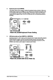
... lead, and a corresponding setting in low power mode) using the connected USB devices. USBPW1-4 12 23 +5V +5VSB (Default) USBPW5-8 P5G41-M LX2/GB 12 23 +5V +5VSB (Default) P5G41-M LX2/GB USB Device Wake Up ASUS P5G41-M LX2 Series 1-9 Keyboard power (3-pin KBPWR) This jumper allows you can supply at least 1A on the keyboard (the default is the...
... lead, and a corresponding setting in low power mode) using the connected USB devices. USBPW1-4 12 23 +5V +5VSB (Default) USBPW5-8 P5G41-M LX2/GB 12 23 +5V +5VSB (Default) P5G41-M LX2/GB USB Device Wake Up ASUS P5G41-M LX2 Series 1-9 Keyboard power (3-pin KBPWR) This jumper allows you can supply at least 1A on the keyboard (the default is the...
User Manual
Page 20
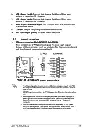
...supply plugs are for details. ATX12V EATXPWR +12V DC +12V DC P5G41-M LX2/GB GND GND +3 Volts +12 Volts +12 Volts +5V Standby Power OK PIN 1 GND +5 Volts GND +5 Volts GND +3 Volts +3 Volts PIN 1 P5G41-M LX2/GB ATX power connectors GND +5 Volts +5 Volts +5 Volts -5 Volts ... connectors completely fit. com/PowerSupplyCalculator/PSCalculator.aspx?SLanguage=en-us for ATX power supply plugs. USB 2.0 ports 3 and 4. COM port. 6. ASUS P5G41-M LX2 Series 1-11 This port is for a PS/2 keyboard. 1.7.2 Internal connectors 1. This 15-pin port is for a VGA monitor or other...
...supply plugs are for details. ATX12V EATXPWR +12V DC +12V DC P5G41-M LX2/GB GND GND +3 Volts +12 Volts +12 Volts +5V Standby Power OK PIN 1 GND +5 Volts GND +5 Volts GND +3 Volts +3 Volts PIN 1 P5G41-M LX2/GB ATX power connectors GND +5 Volts +5 Volts +5 Volts -5 Volts ... connectors completely fit. com/PowerSupplyCalculator/PSCalculator.aspx?SLanguage=en-us for ATX power supply plugs. USB 2.0 ports 3 and 4. COM port. 6. ASUS P5G41-M LX2 Series 1-11 This port is for a PS/2 keyboard. 1.7.2 Internal connectors 1. This 15-pin port is for a VGA monitor or other...
User Manual
Page 21
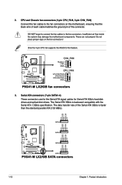
... GND SATA4 GND RSATA_RXN3 RSATA_RXP3 GND RSATA_TXN3 RSATA_TXP3 GND SATA3 GND RSATA_RXN2 RSATA_RXP2 GND RSATA_TXN2 RSATA_TXP2 GND GND RSATA_RXN1 RSATA_RXP1 GND RSATA_TXN1 RSATA_TXP1 GND P5G41-M LX2/GB SATA2 SATA1 P5G41-M LX2/GB SATA connectors 1-12 Chapter 1: Product introduction 2. CPU and Chassis fan connectors (4-pin CPU_FAN, 3-pin CHA_FAN) Connect the fan cables to the fan connectors. Do... the Serial ATA 1.5Gb/s specification. The Serial ATA 3Gb/s is faster than the standard parallel ATA (133 MB/s). Only the 4-pin CPU fan supports the ASUS Q-Fan feature.
... GND SATA4 GND RSATA_RXN3 RSATA_RXP3 GND RSATA_TXN3 RSATA_TXP3 GND SATA3 GND RSATA_RXN2 RSATA_RXP2 GND RSATA_TXN2 RSATA_TXP2 GND GND RSATA_RXN1 RSATA_RXP1 GND RSATA_TXN1 RSATA_TXP1 GND P5G41-M LX2/GB SATA2 SATA1 P5G41-M LX2/GB SATA connectors 1-12 Chapter 1: Product introduction 2. CPU and Chassis fan connectors (4-pin CPU_FAN, 3-pin CHA_FAN) Connect the fan cables to the fan connectors. Do... the Serial ATA 1.5Gb/s specification. The Serial ATA 3Gb/s is faster than the standard parallel ATA (133 MB/s). Only the 4-pin CPU fan supports the ASUS Q-Fan feature.
User Manual
Page 22
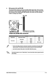
... incorrect insertion when you connect the IDE cable. • Use the 80-conductor IDE cable for the Ultra DMA 100/66 signal cable. ASUS P5G41-M LX2 Series 1-13 IDE connector (40-1 pin PRI_IDE) The onboard IDE connector is set as "Cable-Select," ensure that all other device jumpers have... the same setting. PRI_IDE PIN1 P5G41-M LX2/GB NOTE:Orient the red markings on the IDE ribbon cable to configure your device. Master Slave Master Slave Cable connector Black Black Gray Black...
... incorrect insertion when you connect the IDE cable. • Use the 80-conductor IDE cable for the Ultra DMA 100/66 signal cable. ASUS P5G41-M LX2 Series 1-13 IDE connector (40-1 pin PRI_IDE) The onboard IDE connector is set as "Cable-Select," ensure that all other device jumpers have... the same setting. PRI_IDE PIN1 P5G41-M LX2/GB NOTE:Orient the red markings on the IDE ribbon cable to configure your device. Master Slave Master Slave Cable connector Black Black Gray Black...
User Manual
Page 24
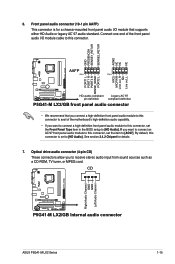
CD Right Audio Channel GND GND Left Audio Channel P5G41-M LX2/GB P5G41-M LX2/GB Internal audio connector ASUS P5G41-M LX2 Series 1-15 6. Front panel audio connector (10-1 pin AAFP) This connector is set the Front Panel Type item in the BIOS setup to [HD Audio]. ...
CD Right Audio Channel GND GND Left Audio Channel P5G41-M LX2/GB P5G41-M LX2/GB Internal audio connector ASUS P5G41-M LX2 Series 1-15 6. Front panel audio connector (10-1 pin AAFP) This connector is set the Front Panel Type item in the BIOS setup to [HD Audio]. ...
User Manual
Page 28
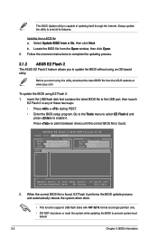
... press to update the BIOS without using an OS‑based utility. Follow the onscreen instructions to complete the updating process. 2.1.2 ASUS EZ Flash 2 The ASUS EZ Flash 2 feature allows you start using EZ Flash 2: 1. Press to switch between drives until the correct BIOS file is ...BIOS to prevent system boot failure! 2-2 Chapter 2: BIOS information ASUSTek EZ Flash 2 BIOS ROM Utility V3.44 FLASH TYPE: MXIC 25L8005 Current ROM BOARD: P5G41-M LX2/GB VER: 0211 (H:00 B:03) DATE: 09/28/2009 Update ROM BOARD: Unknown VER: Unknown DATE: Unknown PATH: A:\ A: Note [Enter] Select or...
... press to update the BIOS without using an OS‑based utility. Follow the onscreen instructions to complete the updating process. 2.1.2 ASUS EZ Flash 2 The ASUS EZ Flash 2 feature allows you start using EZ Flash 2: 1. Press to switch between drives until the correct BIOS file is ...BIOS to prevent system boot failure! 2-2 Chapter 2: BIOS information ASUSTek EZ Flash 2 BIOS ROM Utility V3.44 FLASH TYPE: MXIC 25L8005 Current ROM BOARD: P5G41-M LX2/GB VER: 0211 (H:00 B:03) DATE: 09/28/2009 Update ROM BOARD: Unknown VER: Unknown DATE: Unknown PATH: A:\ A: Note [Enter] Select or...


