P4T533 User Manual
Page 1
Motherboard ® P4T533 User Manual
Motherboard ® P4T533 User Manual
P4T533 User Manual
Page 3
...the BIOS parameters are supplied. • Chapter 5: Software support. Describes the power up sequence with information on the motherboard support CD ROM. • Appendix and Glossary. A summary of the following symbols used in this manual. Optional components and .... iii WARNING! How this guide This user manual contains complete information for installing the ASUS P4T533 motherboard. A list of hardware setup procedures and descriptions of all jumpers and connectors on the motherboard. • Chapter 3: Powering up tasks properly, take note of contents on BIOS ...
...the BIOS parameters are supplied. • Chapter 5: Software support. Describes the power up sequence with information on the motherboard support CD ROM. • Appendix and Glossary. A summary of the following symbols used in this manual. Optional components and .... iii WARNING! How this guide This user manual contains complete information for installing the ASUS P4T533 motherboard. A list of hardware setup procedures and descriptions of all jumpers and connectors on the motherboard. • Chapter 3: Powering up tasks properly, take note of contents on BIOS ...
P4T533 User Manual
Page 4
... used in this guide iii Safety information vi FCC/CDC statements vii ASUS contact information viii P4T533 specifications summary ix Chapter 1: Product introduction 1 Welcome 1 1.1 Package contents 1 1.2 Core Specifications 2 1.3 Special Features 3 1.4 Motherboard Components 4 1.4.1 Component Locations 5 Chapter 2: Hardware information 7 2.1 Motherboard installation 7 2.1.1 Placement direction 7 2.1.2 Screw holes 7 2.2 Motherboard layout 8 2.2.1 Layout contents 9 2.3 Before you proceed 10 2.4 Central Processing Unit (CPU...
... used in this guide iii Safety information vi FCC/CDC statements vii ASUS contact information viii P4T533 specifications summary ix Chapter 1: Product introduction 1 Welcome 1 1.1 Package contents 1 1.2 Core Specifications 2 1.3 Special Features 3 1.4 Motherboard Components 4 1.4.1 Component Locations 5 Chapter 2: Hardware information 7 2.1 Motherboard installation 7 2.1.1 Placement direction 7 2.1.2 Screw holes 7 2.2 Motherboard layout 8 2.2.1 Layout contents 9 2.3 Before you proceed 10 2.4 Central Processing Unit (CPU...
P4T533 User Manual
Page 5
...3.2 Vocal POST Messages 48 3.3 Powering off the computer 50 Chapter 4: BIOS setup 51 4.1 Managing and updating your BIOS 51 4.1.1 Using ASUS EZ Flash to update the BIOS 51 4.1.2 Using AFLASH from a Floppy Disk 53 4.1.3 Updating BIOS procedures 54 4.2 BIOS Setup program 56...Software support 83 5.1 Install an operating system 83 5.2 Support CD information 83 5.3 P4T533 Motherboard Support CD 84 5.4 ASUS PC Probe 86 5.5 ASUS Live Update 91 5.6 3Deep Color Tuner 92 5.7 Winbond Voice Editor 94 5.8 ASUS MyLogo2 98 ™ ...5.9 Multi-Channel Audio Feature Setup 100 5.10 Using the ...
...3.2 Vocal POST Messages 48 3.3 Powering off the computer 50 Chapter 4: BIOS setup 51 4.1 Managing and updating your BIOS 51 4.1.1 Using ASUS EZ Flash to update the BIOS 51 4.1.2 Using AFLASH from a Floppy Disk 53 4.1.3 Updating BIOS procedures 54 4.2 BIOS Setup program 56...Software support 83 5.1 Install an operating system 83 5.2 Support CD information 83 5.3 P4T533 Motherboard Support CD 84 5.4 ASUS PC Probe 86 5.5 ASUS Live Update 91 5.6 3Deep Color Tuner 92 5.7 Winbond Voice Editor 94 5.8 ASUS MyLogo2 98 ™ ...5.9 Multi-Channel Audio Feature Setup 100 5.10 Using the ...

P4T533 User Manual
Page 6
... correctly connected and the power cables are not damaged. If you detect any area where it may become wet. • Mount the motherboard inside a standard PC enclosure. • If you encounter technical problems with the package. • Before use ensure all power cables are... connected. vi Operational safety • Before installing the motherboard and adding new devices, carefully read all the manuals that the power cables for the devices are unplugged before the signal cables are unplugged...
... correctly connected and the power cables are not damaged. If you detect any area where it may become wet. • Mount the motherboard inside a standard PC enclosure. • If you encounter technical problems with the package. • Before use ensure all power cables are... connected. vi Operational safety • Before installing the motherboard and adding new devices, carefully read all the manuals that the power cables for the devices are unplugged before the signal cables are unplugged...
P4T533 User Manual
Page 12
Please refer to page 18 for special information about the requirements for the RIMM memory configuration. ASUS P4T533 motherboard Special Notice!
Please refer to page 18 for special information about the requirements for the RIMM memory configuration. ASUS P4T533 motherboard Special Notice!
P4T533 User Manual
Page 13
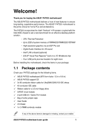
... I/O Windbond chip ~ Four USB ports plus two headers for eight more Before installing the motherboard, check the items in your package: 1.1 Package contents Check your P4T533 package for the following items. ASUS P4T533 motherboard (ATX form factor: 12-in x 9.6-in) ASUS P4T533 support CD 3x 80-conductor ribbon cable for UltraDMA/33/66/100 IDE drives 40...
... I/O Windbond chip ~ Four USB ports plus two headers for eight more Before installing the motherboard, check the items in your package: 1.1 Package contents Check your P4T533 package for the following items. ASUS P4T533 motherboard (ATX form factor: 12-in x 9.6-in) ASUS P4T533 support CD 3x 80-conductor ribbon cable for UltraDMA/33/66/100 IDE drives 40...
P4T533 User Manual
Page 14
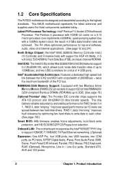
... 1, data "mirroring," improves fault tolerance by optimizing two hard disks to write data to the highest standards. 1.2 Core Specifications The P4T533 motherboard is designed and assembled according to each other. (See page 100.) Smart BIOS: 4Mb firmware enables Vcore adjustments, boot block write protection...Promise® chip: The Promise IDE controller chips supports the ATA-133 protocol and UltraDMA/133 data transfer speeds. This ASUS motherboard represents the latest advances and supplies users the finest components available today... Intel ICH2: The Intel I /O tasks are achieved. and ...
... 1, data "mirroring," improves fault tolerance by optimizing two hard disks to write data to the highest standards. 1.2 Core Specifications The P4T533 motherboard is designed and assembled according to each other. (See page 100.) Smart BIOS: 4Mb firmware enables Vcore adjustments, boot block write protection...Promise® chip: The Promise IDE controller chips supports the ATA-133 protocol and UltraDMA/133 data transfer speeds. This ASUS motherboard represents the latest advances and supplies users the finest components available today... Intel ICH2: The Intel I /O tasks are achieved. and ...
P4T533 User Manual
Page 15
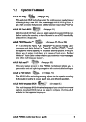
... Winbond™ Voice Editor software helpsa you of system boot status and causes of boot errors. Visit the ASUS website for the supported languages. ASUS P4T533 motherboard user guide 3 ASUS MyLogo2™ (See page 98.) This new feature present in the P4T533 motherboard allows you can easily update the system BIOS even before loading the operating system...
... Winbond™ Voice Editor software helpsa you of system boot status and causes of boot errors. Visit the ASUS website for the supported languages. ASUS P4T533 motherboard user guide 3 ASUS MyLogo2™ (See page 98.) This new feature present in the P4T533 motherboard allows you can easily update the system BIOS even before loading the operating system...

P4T533 User Manual
Page 16
...3/4 39 2 Serial Ports (COM1/2 40 USB 1.1 Connectors (Port 1/2 41 PS/2 Keyboard Connector purple) 42 System Voltage Monitor (integrated in ASUS ASIC 11 Onboard LED 24 Onboard AGP Warning LED 7 Modem Connector 29 RJ45 Connector (optional 35 (Audio Models Only) S/PDIF Connector 25 Audio... Connector 6 ATX12V Power Supply Connector 1 ATX 4 Chapter 1: Product introduction Sufficient knowledge of specifications prevents accidental damage. 1.4 Motherboard Components Before installing the P4T533 motherboard, take time to familiarize yourself with its configuration: understanding the...
...3/4 39 2 Serial Ports (COM1/2 40 USB 1.1 Connectors (Port 1/2 41 PS/2 Keyboard Connector purple) 42 System Voltage Monitor (integrated in ASUS ASIC 11 Onboard LED 24 Onboard AGP Warning LED 7 Modem Connector 29 RJ45 Connector (optional 35 (Audio Models Only) S/PDIF Connector 25 Audio... Connector 6 ATX12V Power Supply Connector 1 ATX 4 Chapter 1: Product introduction Sufficient knowledge of specifications prevents accidental damage. 1.4 Motherboard Components Before installing the P4T533 motherboard, take time to familiarize yourself with its configuration: understanding the...
P4T533 User Manual
Page 18
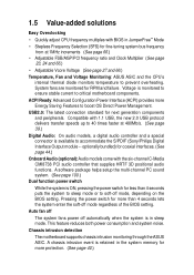
Chassis intrusion detection The motherboard supports chassis intrusion monitoring through the ASUS ASIC. 1.5 Value-added solutions Easy Overclocking • Quickly adjust CPU frequency multiples with the six-channel C-Media CMI8738 PCI audio controller that ... OS Direct Power Management. USB2.0: The latest connection standard for RPM and failure. A chassis intrusion event is monitored to ensure stable current to critical motherboard components. Voltage is retained in the system memory for more protection. (See page 40.) Compatible with 1.1 USB, the new 2.0 USB protocol delivers ...
Chassis intrusion detection The motherboard supports chassis intrusion monitoring through the ASUS ASIC. 1.5 Value-added solutions Easy Overclocking • Quickly adjust CPU frequency multiples with the six-channel C-Media CMI8738 PCI audio controller that ... OS Direct Power Management. USB2.0: The latest connection standard for RPM and failure. A chassis intrusion event is monitored to ensure stable current to critical motherboard components. Voltage is retained in the system memory for more protection. (See page 40.) Compatible with 1.1 USB, the new 2.0 USB protocol delivers ...

P4T533 User Manual
Page 20
ASUS P4T533 motherboard
ASUS P4T533 motherboard
P4T533 User Manual
Page 21
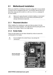
...chassis. Place this side towards the rear of the chassis ASUS P4T533 motherboard user guide 7 Refer to the image below. 2.1.2 Screw holes Place nine (9) screws into the holes indicated by circles to secure the motherboard to the rear part of the chassis. Do not overtighten ...! Doing so may cause you physical injury and damage motherboard components. 2.1.1 Placement direction When installing the motherboard, make sure that you install the motherboard, study the configuration of your chassis to do so may damage the motherboard. The P4T533 uses the ATX form factor that measures 24.5 cm...
...chassis. Place this side towards the rear of the chassis ASUS P4T533 motherboard user guide 7 Refer to the image below. 2.1.2 Screw holes Place nine (9) screws into the holes indicated by circles to secure the motherboard to the rear part of the chassis. Do not overtighten ...! Doing so may cause you physical injury and damage motherboard components. 2.1.1 Placement direction When installing the motherboard, make sure that you install the motherboard, study the configuration of your chassis to do so may damage the motherboard. The P4T533 uses the ATX form factor that measures 24.5 cm...
P4T533 User Manual
Page 22
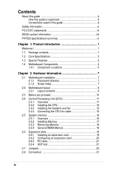
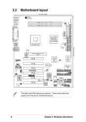
...478 Intel 850E Memory Controller Hub (MCH) TRPWR CPU_FAN ATX12V DSWF Accelerated Graphics Port AGP PCI1 Intel I/O Controller Hub (ICH2) CLCMOS ASUS ASIC with Hardware Monitor PCI2 PCI3 P4T533 PCI4 ® PCI5 PCI6 CR2032 3V Lithium Cell CMOS Power SEC_RAID Super I/O CH_FAN PRI_RAID JEN SMB PROMISE PDC20276 ATA133 Controller DSWMUL ...SMARTCARD USB2.0 Controller USB11_23 Speech Controller SMART USB20_12 SPEECH AFPANEL HDLED PANEL The audio and LAN features are grayed out in the above motherboard layout. 8 Chapter 2: Hardware information These components are optional.
...478 Intel 850E Memory Controller Hub (MCH) TRPWR CPU_FAN ATX12V DSWF Accelerated Graphics Port AGP PCI1 Intel I/O Controller Hub (ICH2) CLCMOS ASUS ASIC with Hardware Monitor PCI2 PCI3 P4T533 PCI4 ® PCI5 PCI6 CR2032 3V Lithium Cell CMOS Power SEC_RAID Super I/O CH_FAN PRI_RAID JEN SMB PROMISE PDC20276 ATA133 Controller DSWMUL ...SMARTCARD USB2.0 Controller USB11_23 Speech Controller SMART USB20_12 SPEECH AFPANEL HDLED PANEL The audio and LAN features are grayed out in the above motherboard layout. 8 Chapter 2: Hardware information These components are optional.

P4T533 User Manual
Page 23
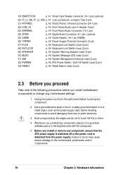
... p. 13 Installing the Heatsink and Fan 3) Memory p. 16 System Memory Support 4) PCI 1/2/3/4/5/6 p. 19 32-bit PCI Bus Expansion Slots 5) AGP Pro p. 21 Accelerated Graphics Slot Motherboard Settings (Switches and Jumpers) 1) JEN p. 22 JumperFree Mode Setting (Disable/Enable) 2) DSW1 p. 23 CPU External Frequency Selection (Switches 1-5) 3) DSW p. 24 CPU Frequency Multiple Setting... p. 39 USB 2.0 Headers (10-1 pin) 17) CD, AUX, MODEM p. 40 Internal Audio Connectors (Three 4-1 pin) (optional) 18) CHASSIS p. 40 Chassis Open Alarm Lead (4-1 pin) ASUS P4T533 motherboard user guide 9
... p. 13 Installing the Heatsink and Fan 3) Memory p. 16 System Memory Support 4) PCI 1/2/3/4/5/6 p. 19 32-bit PCI Bus Expansion Slots 5) AGP Pro p. 21 Accelerated Graphics Slot Motherboard Settings (Switches and Jumpers) 1) JEN p. 22 JumperFree Mode Setting (Disable/Enable) 2) DSW1 p. 23 CPU External Frequency Selection (Switches 1-5) 3) DSW p. 24 CPU Frequency Multiple Setting... p. 39 USB 2.0 Headers (10-1 pin) 17) CD, AUX, MODEM p. 40 Internal Audio Connectors (Three 4-1 pin) (optional) 18) CHASSIS p. 40 Chassis Open Alarm Lead (4-1 pin) ASUS P4T533 motherboard user guide 9
P4T533 User Manual
Page 24
... may cause severe damage to static electricity. 3. Whenever you uninstall any component, ensure that came with the component. 5 Before you install motherboard components or change any component. 2. Failure to do not to touch the ICs on a grounded antistatic pad or in the bag that...SMARTCON p. 41 Smart Card Reader connector (14-1 pin) (optional) 20) FP_LO_SWL, FP_LO_SWR p. 41 Line-out Selector Jumpers (Two 2 pin) 21) AFPANEL p. 42 ASUS iPanel / Infrared Connector (24-1 pin) 22) LINE_IN p. 43 Front Panel Audio Line In Header (5 pin) 23) AAPANEL p. 43 Front Panel Audio Connector (10...
... may cause severe damage to static electricity. 3. Whenever you uninstall any component, ensure that came with the component. 5 Before you install motherboard components or change any component. 2. Failure to do not to touch the ICs on a grounded antistatic pad or in the bag that...SMARTCON p. 41 Smart Card Reader connector (14-1 pin) (optional) 20) FP_LO_SWL, FP_LO_SWR p. 41 Line-out Selector Jumpers (Two 2 pin) 21) AFPANEL p. 42 ASUS iPanel / Infrared Connector (24-1 pin) 22) LINE_IN p. 43 Front Panel Audio Line In Header (5 pin) 23) AAPANEL p. 43 Front Panel Audio Connector (10...

P4T533 User Manual
Page 25
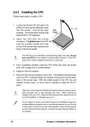
... improve system performance by allowing higher processor frequencies, faster execution of integer instructions, and a data transfer rate of the CPU socket. ASUS P4T533 motherboard user guide 11 2.4 Central Processing Unit (CPU) 2.4.1 Overview The motherboard comes with a surface mount 478-pin Zero Insertion Force (ZIF) socket. This mark indicates the processor Pin 1 that the CPU...
... improve system performance by allowing higher processor frequencies, faster execution of integer instructions, and a data transfer rate of the CPU socket. ASUS P4T533 motherboard user guide 11 2.4 Central Processing Unit (CPU) 2.4.1 Overview The motherboard comes with a surface mount 478-pin Zero Insertion Force (ZIF) socket. This mark indicates the processor Pin 1 that the CPU...
P4T533 User Manual
Page 26
.... Install an Intel fan heatsink. 5. Place the CPU fan and heatsink on the CPU. The heatsink should drop easily into the socket to scrape the motherboard surface when mounting a clampstyle processor fan, or else damage may occur. When mounting a heatsink onto your Socket 478 processor or else boot-up may occur...
.... Install an Intel fan heatsink. 5. Place the CPU fan and heatsink on the CPU. The heatsink should drop easily into the socket to scrape the motherboard surface when mounting a clampstyle processor fan, or else damage may occur. When mounting a heatsink onto your Socket 478 processor or else boot-up may occur...

P4T533 User Manual
Page 27
... to remove the retention module base when installing the CPU or installing other motherboard components. In case you buy a CPU separately, make sure that the heatsink fits properly on the motherboard upon purchase. Place the heatsink on top of the installed CPU, making ... heatsink and fan assembly to install the CPU heatsink and fan. 1. Follow these steps to ensure optimum thermal condition and performance. ASUS P4T533 motherboard user guide 13 CPU Heatsink Retention Module Base Your boxed Intel Pentium 4 478 Processor package should come with installation instructions for the...
... to remove the retention module base when installing the CPU or installing other motherboard components. In case you buy a CPU separately, make sure that the heatsink fits properly on the motherboard upon purchase. Place the heatsink on top of the installed CPU, making ... heatsink and fan assembly to install the CPU heatsink and fan. 1. Follow these steps to ensure optimum thermal condition and performance. ASUS P4T533 motherboard user guide 13 CPU Heatsink Retention Module Base Your boxed Intel Pentium 4 478 Processor package should come with installation instructions for the...

P4T533 User Manual
Page 29
When secure, the retention locks should point to opposite directions. 2.4.4 Connecting the CPU fan cable When the fan, heatsink, and the retention mechanism are in place, connect the CPU fan cable to connect the CPU fan connector! ASUS P4T533 motherboard user guide 15 3. CPU Fan Connector (CPUFAN1) Don't forget to the connector on the retention mechanism to secure the heatsink and fan to plug this connector. Push down the locks on the motherboard labeled CPUFAN1. Hardware monitoring errors may occur if you fail to the module base.
When secure, the retention locks should point to opposite directions. 2.4.4 Connecting the CPU fan cable When the fan, heatsink, and the retention mechanism are in place, connect the CPU fan cable to connect the CPU fan connector! ASUS P4T533 motherboard user guide 15 3. CPU Fan Connector (CPUFAN1) Don't forget to the connector on the retention mechanism to secure the heatsink and fan to plug this connector. Push down the locks on the motherboard labeled CPUFAN1. Hardware monitoring errors may occur if you fail to the module base.


