
P4T533 User Manual
Page 30
... b. 128 / 256 / 512 MB RDRAM C-RIMM RIMM1 RIMM2 c. 128 / 256 / 512 MB RDRAM 128 / 256 / 512 MB RDRAM RIMM1 RIMM2 16 Chapter 2: Hardware information The diagram below shows the various combinations for inserting RIMMs.) a. 2.5 System memory 2.5.1 Overview This motherboard has two 232-pin Rambus Inline Memory Modules (RIMM) sockets. These sockets...
... b. 128 / 256 / 512 MB RDRAM C-RIMM RIMM1 RIMM2 c. 128 / 256 / 512 MB RDRAM 128 / 256 / 512 MB RDRAM RIMM1 RIMM2 16 Chapter 2: Hardware information The diagram below shows the various combinations for inserting RIMMs.) a. 2.5 System memory 2.5.1 Overview This motherboard has two 232-pin Rambus Inline Memory Modules (RIMM) sockets. These sockets...
P4T533 User Manual
Page 60
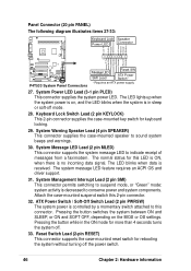
...supplies the system power LED. The LED blinks when data is no incoming data signal. Panel Connector (20 pin PANEL) The following diagram illustrates items 27-33: Keyboard Lock Speaker Power LED Connector +5 V PLED Keylock Ground +5V Ground Ground Speaker +5 V MLED ExtSMI# Ground... PWR Ground Reset Ground P4T533 ® P4T533 System Panel Connectors Message LED SMI Lead Reset SW ATX Power Switch* * Requires an ATX power supply. 27. The normal status for more...
...supplies the system power LED. The LED blinks when data is no incoming data signal. Panel Connector (20 pin PANEL) The following diagram illustrates items 27-33: Keyboard Lock Speaker Power LED Connector +5 V PLED Keylock Ground +5V Ground Ground Speaker +5 V MLED ExtSMI# Ground... PWR Ground Reset Ground P4T533 ® P4T533 System Panel Connectors Message LED SMI Lead Reset SW ATX Power Switch* * Requires an ATX power supply. 27. The normal status for more...
P4T533 User Manual
Page 121
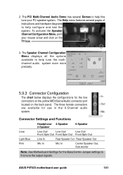
...tune your mouse arrow and click on the back panel. The PCI Multi-Channel Audio Demo has several pages of instructions and hardware diagrams to fine tune the output signals. The Help menu features several Demos to help configure and test the system. To activate the ... The chart below displays the configurations for the line In connectors on the yellow MIDI/Game/Audio connector port located on the TV box. 3. ASUS P4T533 motherboard user guide 101 2. Mic Connector Settings and Functions Headphone/ 4-Speaker 2-Speaker 6-Speaker Lime Line Out/ Line Out/ Line Out/ Front ...
...tune your mouse arrow and click on the back panel. The PCI Multi-Channel Audio Demo has several pages of instructions and hardware diagrams to fine tune the output signals. The Help menu features several Demos to help configure and test the system. To activate the ... The chart below displays the configurations for the line In connectors on the yellow MIDI/Game/Audio connector port located on the TV box. 3. ASUS P4T533 motherboard user guide 101 2. Mic Connector Settings and Functions Headphone/ 4-Speaker 2-Speaker 6-Speaker Lime Line Out/ Line Out/ Line Out/ Front ...

