
P4T533 User Manual
Page 9
...Chipset Intel 82850E MCH Intel 82801BA ICH2 (B4) Front Side Bus (FSB) 533 / 400 MHz Memory 2 x 232-pin 32-bit RIMM4200/3200-compliant Rambus DRAMs (RDRAMs) up to 2GB. memory. P4T533 specifications summary CPU Socket 478 for 2 additional USB ports CPU/Power/Chassis fan connectors 20-pin/4-pin ATX power connectors IDE LED/Power LED connectors Chassis intrusion and SMBus Front Panel/ SIR connectors GAME/MIDI connector S/PDIF In/Out connector Smart card connector(optional) iPanel front panel control connector CD/AUX/Modem audio connectors (optional) Front panel audio connector (optional...
...Chipset Intel 82850E MCH Intel 82801BA ICH2 (B4) Front Side Bus (FSB) 533 / 400 MHz Memory 2 x 232-pin 32-bit RIMM4200/3200-compliant Rambus DRAMs (RDRAMs) up to 2GB. memory. P4T533 specifications summary CPU Socket 478 for 2 additional USB ports CPU/Power/Chassis fan connectors 20-pin/4-pin ATX power connectors IDE LED/Power LED connectors Chassis intrusion and SMBus Front Panel/ SIR connectors GAME/MIDI connector S/PDIF In/Out connector Smart card connector(optional) iPanel front panel control connector CD/AUX/Modem audio connectors (optional) Front panel audio connector (optional...
P4T533 User Manual
Page 14
... AGP Pro, four USB ports, two USB headers, two COM ports, six PCI slots, S/PDIF Digital Audio, iPanel, Front Audio Panel, SMB, Game, Front Panel/CIR Infrared, Parallel, PS/2 Mouse, PS/2 Keyboard, RJ45 (Optional), Microphone, Line-In / Line-Out jacks, Standard ATX, AUX and 12V power. 2 Chapter 1: Product introduction RAID 0, data "striping," improves speed performance as I /O Controller and Firmware Hub) with two Rambus Inline Memory Module (RIMM) 232-pin sockets to support 32-bit Intel...
... AGP Pro, four USB ports, two USB headers, two COM ports, six PCI slots, S/PDIF Digital Audio, iPanel, Front Audio Panel, SMB, Game, Front Panel/CIR Infrared, Parallel, PS/2 Mouse, PS/2 Keyboard, RJ45 (Optional), Microphone, Line-In / Line-Out jacks, Standard ATX, AUX and 12V power. 2 Chapter 1: Product introduction RAID 0, data "striping," improves speed performance as I /O Controller and Firmware Hub) with two Rambus Inline Memory Module (RIMM) 232-pin sockets to support 32-bit Intel...

P4T533 User Manual
Page 16
...2 32-bit PC1066/800 Memory RIMMs 4 6 PCI Slots 27 Accelerated Graphics Port (AGP) Pro Slot 32 Floppy Disk Drive Connector 8 2 IDE Connectors (UltraDMA/133 Support 10 2 IDE Connectors (RAID Support 14 Smart Card Connector 16 iPanel / Infrared Connector 17 System Panel Connector 18 USB Headers (USB1.1 20 USB Headers (USB2.0 21 Game Header 31 PS/2 Mouse Connector green) 33 Parallel Port 34 USB 2.0 Connectors (Port 3/4 39 2 Serial Ports (COM1/2 40 USB 1.1 Connectors (Port 1/2 41 PS/2 Keyboard Connector purple) 42 System Voltage Monitor (integrated in ASUS ASIC 11 Onboard LED 24...
...2 32-bit PC1066/800 Memory RIMMs 4 6 PCI Slots 27 Accelerated Graphics Port (AGP) Pro Slot 32 Floppy Disk Drive Connector 8 2 IDE Connectors (UltraDMA/133 Support 10 2 IDE Connectors (RAID Support 14 Smart Card Connector 16 iPanel / Infrared Connector 17 System Panel Connector 18 USB Headers (USB1.1 20 USB Headers (USB2.0 21 Game Header 31 PS/2 Mouse Connector green) 33 Parallel Port 34 USB 2.0 Connectors (Port 3/4 39 2 Serial Ports (COM1/2 40 USB 1.1 Connectors (Port 1/2 41 PS/2 Keyboard Connector purple) 42 System Voltage Monitor (integrated in ASUS ASIC 11 Onboard LED 24...
P4T533 User Manual
Page 18
... BIOS setting. Compatible with the six-channel C-Media CMI8738 PCI audio controller that supplies HRTF 3D positional audio functions. A software package helps setup the multi-channel PC sound system. (See page 100.) Dual function power switch While the system is ON, pressing the power switch for more than 4 seconds puts the system to sleep mode or to prevent overheating. Voltage is retained in sleep mode. optionally bundled) for RPM and failure. This feature reduces both power...
... BIOS setting. Compatible with the six-channel C-Media CMI8738 PCI audio controller that supplies HRTF 3D positional audio functions. A software package helps setup the multi-channel PC sound system. (See page 100.) Dual function power switch While the system is ON, pressing the power switch for more than 4 seconds puts the system to sleep mode or to prevent overheating. Voltage is retained in sleep mode. optionally bundled) for RPM and failure. This feature reduces both power...

P4T533 User Manual
Page 23
... CPU Frequency Multiple Setting (Switches 1-4) 4) USB_EN p. 25 USB Header (Enable/Disable) 5) USBPWR01, 23 p. 25 USB Device Wake-up (+5V / +5VSB) 6) BCS1, BCS2 p. 26 Bass Center Setting (Bass Center / Center Bass) 7) KBPWR p. 26 Keyboard Wake Up (+5V, +5VSB) 8) OVER_VOLT p. 27 CPU Over Voltage Setting (Normal / OverVoltage) 9) SPEECH p. 27 Speaker Selector (Buzzer / Lineout) 10) RAID_SW p. 28 RAID IDE Setting (Enable / Disable) 11) CLRTC p. 29 Clear RTC RAM Connectors 1) PS2KBMS p. 31 PS/2 Mouse Port (6 pin female) 2) PS2KBMS p. 31 PS/2 Keyboard Port (6 pin female) 3) USB...
... CPU Frequency Multiple Setting (Switches 1-4) 4) USB_EN p. 25 USB Header (Enable/Disable) 5) USBPWR01, 23 p. 25 USB Device Wake-up (+5V / +5VSB) 6) BCS1, BCS2 p. 26 Bass Center Setting (Bass Center / Center Bass) 7) KBPWR p. 26 Keyboard Wake Up (+5V, +5VSB) 8) OVER_VOLT p. 27 CPU Over Voltage Setting (Normal / OverVoltage) 9) SPEECH p. 27 Speaker Selector (Buzzer / Lineout) 10) RAID_SW p. 28 RAID IDE Setting (Enable / Disable) 11) CLRTC p. 29 Clear RTC RAM Connectors 1) PS2KBMS p. 31 PS/2 Mouse Port (6 pin female) 2) PS2KBMS p. 31 PS/2 Keyboard Port (6 pin female) 3) USB...
P4T533 User Manual
Page 34
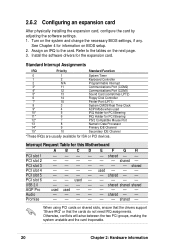
... Floppy Disk Controller 7* 15 Printer Port (LPT1) 8 3 System CMOS/Real Time Clock 9* 4 ACPI Mode when used 10* 5 IRQ Holder for PCI Steering 11* 6 IRQ Holder for PCI Steering 12* 7 PS/2 Compatible Mouse Port 13 8 Numeric Data Processor 14* 9 Primary IDE Channel 15* 10 Secondary IDE Channel *These IRQs are usually available for this Motherboard ABCD E F GH PCI slot 1 PCI slot 2 - - - - - Interrupt Request Table for ISA or PCI devices. shared - - - - used shared shared shared AGP Pro Audio used used - - - When using PCI cards on...
... Floppy Disk Controller 7* 15 Printer Port (LPT1) 8 3 System CMOS/Real Time Clock 9* 4 ACPI Mode when used 10* 5 IRQ Holder for PCI Steering 11* 6 IRQ Holder for PCI Steering 12* 7 PS/2 Compatible Mouse Port 13 8 Numeric Data Processor 14* 9 Primary IDE Channel 15* 10 Secondary IDE Channel *These IRQs are usually available for this Motherboard ABCD E F GH PCI slot 1 PCI slot 2 - - - - - Interrupt Request Table for ISA or PCI devices. shared - - - - used shared shared shared AGP Pro Audio used used - - - When using PCI cards on...

P4T533 User Manual
Page 35
ASUS P4T533 motherboard user guide 21 This motherboard does not support 3.3V AGP cards; P4T533 ® Keyed for 1.5v P4T533 Accelerated Graphics Port (AGP) To avoid damaging your AGP/AGP Pro graphics card, the power supply should be unplugged before inserting your graphics card into the slot. 2.6.3 PCI slots There are six 32-bit PCI slots in this motherboard. if a 3.3V card is inserted, the red LED warning light lights up and the board will not power up; The following figure shows a LAN card installed on a PCI slot. 2.6.4 AGP...
ASUS P4T533 motherboard user guide 21 This motherboard does not support 3.3V AGP cards; P4T533 ® Keyed for 1.5v P4T533 Accelerated Graphics Port (AGP) To avoid damaging your AGP/AGP Pro graphics card, the power supply should be unplugged before inserting your graphics card into the slot. 2.6.3 PCI slots There are six 32-bit PCI slots in this motherboard. if a 3.3V card is inserted, the red LED warning light lights up and the board will not power up; The following figure shows a LAN card installed on a PCI slot. 2.6.4 AGP...
P4T533 User Manual
Page 40
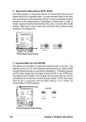
... pin BCS1, BCS2) Use these jumpers in order to reroute signals among the internal leads of the Line-In, Line-Out, Mic female sockets. No audio standard exists for 4 or 6 speaker audio. Keyboard Wake Up (3 pin KBPWR) This allows you set to Enable but do not have the correct ATX power supply. The default is set this to [1-2], +5V, which disables keyboard power up (by pressing ) . Select +5VSB to disable or enable the keyboard power...
... pin BCS1, BCS2) Use these jumpers in order to reroute signals among the internal leads of the Line-In, Line-Out, Mic female sockets. No audio standard exists for 4 or 6 speaker audio. Keyboard Wake Up (3 pin KBPWR) This allows you set to Enable but do not have the correct ATX power supply. The default is set this to [1-2], +5V, which disables keyboard power up (by pressing ) . Select +5VSB to disable or enable the keyboard power...
P4T533 User Manual
Page 49
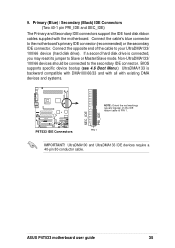
... mode. Non-UltraDMA133/ 100/66 devices should be connected to the motherboard's primary IDE connector (recommended) or the secondary IDE connector. BIOS supports specific device bootup (see 4.6 Boot Menu.) UltraDMA/133 is connected, you may reset its jumper to your UltraDMA133/ 100/66 device (hard disk drive). ASUS P4T533 motherboard user guide 35 9. Connect the cable's blue connector to the secondary IDE connector. Primary (Blue) / Secondary (Black) IDE Connectors (Two 40-1 pin PRI_IDE and SEC_IDE) The Primary and Secondary IDE connectors support the IDE hard disk ribbon cables...
... mode. Non-UltraDMA133/ 100/66 devices should be connected to the motherboard's primary IDE connector (recommended) or the secondary IDE connector. BIOS supports specific device bootup (see 4.6 Boot Menu.) UltraDMA/133 is connected, you may reset its jumper to your UltraDMA133/ 100/66 device (hard disk drive). ASUS P4T533 motherboard user guide 35 9. Connect the cable's blue connector to the secondary IDE connector. Primary (Blue) / Secondary (Black) IDE Connectors (Two 40-1 pin PRI_IDE and SEC_IDE) The Primary and Secondary IDE connectors support the IDE hard disk ribbon cables...
P4T533 User Manual
Page 50
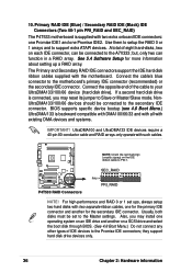
...; P4T533 RAID Connectors SEC_RAID PIN 1 PRI_RAID NOTE! they support hard disk drive devices only. 36 Chapter 2: Hardware information Use them to setup the RAID 0 or 1 arrays and to the secondary IDE connector. The Primary and Secondary RAID IDE connectors support the IDE hard disk ribbon cables supplied with existing DMA devices and systems. IMPORTANT! NonUltraDMA133/100/66 devices should be connected to support extra ATAPI devices. Connect the opposite end of IDE devices to your UltraDMA133/100/66 device (hard disk drive). BIOS supports specific device bootup (see 4.6 Boot Menu...
...; P4T533 RAID Connectors SEC_RAID PIN 1 PRI_RAID NOTE! they support hard disk drive devices only. 36 Chapter 2: Hardware information Use them to setup the RAID 0 or 1 arrays and to the secondary IDE connector. The Primary and Secondary RAID IDE connectors support the IDE hard disk ribbon cables supplied with existing DMA devices and systems. IMPORTANT! NonUltraDMA133/100/66 devices should be connected to support extra ATAPI devices. Connect the opposite end of IDE devices to your UltraDMA133/100/66 device (hard disk drive). BIOS supports specific device bootup (see 4.6 Boot Menu...
P4T533 User Manual
Page 65
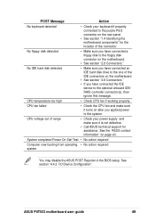
... CPU fan if working properly. CPU fan failed • Check the CPU fan and make sure it turns on the rear panel. • See section "1.4 Identifying the motherboard components" for assistance. ASUS P4T533 motherboard user guide 49 No floppy disk detected • Make sure you have connected the IDE device to the system. POST Message Action No keyboard detected • Check your power supply and make sure it is not defective. • Call ASUS technical support...
... CPU fan if working properly. CPU fan failed • Check the CPU fan and make sure it turns on the rear panel. • See section "1.4 Identifying the motherboard components" for assistance. ASUS P4T533 motherboard user guide 49 No floppy disk detected • Make sure you have connected the IDE device to the system. POST Message Action No keyboard detected • Check your power supply and make sure it is not defective. • Call ASUS technical support...
P4T533 User Manual
Page 75
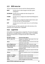
... various setup menus. BOOT Use this menu to enable and make changes to locate and load the Operating System. ADVANCED Use this menu to configure the default system device used to the basic system configuration. The following table lists the keys found in the legend bar with the following selections: MAIN Use this menu to make changes to its Setup Defaults Saves changes and exits Setup ASUS P4T533 motherboard user guide 57 Navigation Key(s) Function Description or Displays the General Help screen from...
... various setup menus. BOOT Use this menu to enable and make changes to locate and load the Operating System. ADVANCED Use this menu to configure the default system device used to the basic system configuration. The following table lists the keys found in the legend bar with the following selections: MAIN Use this menu to make changes to its Setup Defaults Saves changes and exits Setup ASUS P4T533 motherboard user guide 57 Navigation Key(s) Function Description or Displays the General Help screen from...
P4T533 User Manual
Page 86
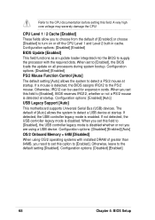
... update loader integrated into the BIOS to supply the processor with installed DRAM of greater than 64MB, you need to set this field to [Disabled], the USB controller legacy mode is disabled whether or not you set to [Enabled], the BIOS loads the update on or off the CPU Level 1 and Level 2 built-in cache. Configuration options: [Enabled] [Auto] USB Legacy Support [Auto] This motherboard supports Universal Serial Bus (USB) devices. If detected, the USB controller legacy mode is disabled. If not detected, the USB controller legacy mode is enabled. When you are using...
... update loader integrated into the BIOS to supply the processor with installed DRAM of greater than 64MB, you need to set this field to [Disabled], the USB controller legacy mode is disabled whether or not you set to [Enabled], the BIOS loads the update on or off the CPU Level 1 and Level 2 built-in cache. Configuration options: [Enabled] [Auto] USB Legacy Support [Auto] This motherboard supports Universal Serial Bus (USB) devices. If detected, the USB controller legacy mode is disabled. If not detected, the USB controller legacy mode is enabled. When you are using...
P4T533 User Manual
Page 89
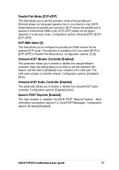
... [Enabled] This field enables or disables the ASUS POST Reporter™feature. Keep the setting [Auto] if you to configure the parallel port DMA channel for the selected ECP mode. Set this field to [Disabled] if you to enable or disable the onboard AC97 audio controller. This selection is available in section 3.2, Vocal POST Messages. ASUS P4T533 motherboard user guide 71 Configuration options: [1] [3] Onboard AC97 Modem Controller [Enabled] This parameter allows you installed a PCI LAN card. Configuration options: [Disabled] [Auto] Onboard AC97 Audio Controller [Enabled...
... [Enabled] This field enables or disables the ASUS POST Reporter™feature. Keep the setting [Auto] if you to configure the parallel port DMA channel for the selected ECP mode. Set this field to [Disabled] if you to enable or disable the onboard AC97 audio controller. This selection is available in section 3.2, Vocal POST Messages. ASUS P4T533 motherboard user guide 71 Configuration options: [1] [3] Onboard AC97 Modem Controller [Enabled] This parameter allows you installed a PCI LAN card. Configuration options: [Disabled] [Auto] Onboard AC97 Audio Controller [Enabled...

P4T533 User Manual
Page 90
... the setting [Disabled] if you to connect USB devices. Setting this field to use the USB feature. 4.4.3 PCI Configuration Slot 1/5, 2, 3, 4, 6 IRQ [Auto] These fields automatically assign the IRQ for each field is [Auto], which utilizes auto-routing to determine IRQ assignments. Configuration options: [Auto] [NA] [3] [4] [5] [7] [9] [10] [11] [12] [14] [15] PCI/VGA Palette Snoop [Disabled] Some non-standard VGA cards, like graphics accelerators or MPEG video cards, may not show colors properly. USB Function [Both] This motherboard supports Universal Serial Bus (USB) devices.
... the setting [Disabled] if you to connect USB devices. Setting this field to use the USB feature. 4.4.3 PCI Configuration Slot 1/5, 2, 3, 4, 6 IRQ [Auto] These fields automatically assign the IRQ for each field is [Auto], which utilizes auto-routing to determine IRQ assignments. Configuration options: [Auto] [NA] [3] [4] [5] [7] [9] [10] [11] [12] [14] [15] PCI/VGA Palette Snoop [Disabled] Some non-standard VGA cards, like graphics accelerators or MPEG video cards, may not show colors properly. USB Function [Both] This motherboard supports Universal Serial Bus (USB) devices.
P4T533 User Manual
Page 103
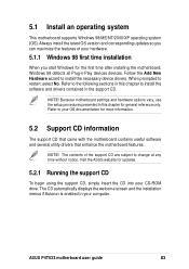
... with the motherboard contains useful software and several utility drivers that enhance the motherboard features. ASUS P4T533 motherboard user guide 83 When prompted to install the necessary device drivers. The CD automatically displays the welcome screen and the installation menus if Autorun is enabled in the support CD. NOTE! NOTE! Visit the ASUS website for the first time after installing the motherboard, Windows 98 detects all Plug-n-Play devices devices. 5.1 Install an operating system This motherboard supports Windows 98/ME...
... with the motherboard contains useful software and several utility drivers that enhance the motherboard features. ASUS P4T533 motherboard user guide 83 When prompted to install the necessary device drivers. The CD automatically displays the welcome screen and the installation menus if Autorun is enabled in the support CD. NOTE! NOTE! Visit the ASUS website for the first time after installing the motherboard, Windows 98 detects all Plug-n-Play devices devices. 5.1 Install an operating system This motherboard supports Windows 98/ME...
P4T533 User Manual
Page 104
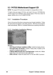
...-channel audio application. • USB 2.0 Driver: Installs the latest driver for operating instructions. 5.3.2 Available Installation Menus Drivers: • Intel Chipset Software Installation Utility: Installs the display drivers. • Intel Application Accelerator: Installs a handy utility to 6. If the menu does not appear, double-click or run D:\ASSETUP.EXE. 5.3.1 Installation Procedure Click on the setup screens. 5.3 P4T533 Motherboard Support CD NOTE: The support CD contents are subject to begin using your support CD disc, just insert it into your CD-ROM drive...
...-channel audio application. • USB 2.0 Driver: Installs the latest driver for operating instructions. 5.3.2 Available Installation Menus Drivers: • Intel Chipset Software Installation Utility: Installs the display drivers. • Intel Application Accelerator: Installs a handy utility to 6. If the menu does not appear, double-click or run D:\ASSETUP.EXE. 5.3.1 Installation Procedure Click on the setup screens. 5.3 P4T533 Motherboard Support CD NOTE: The support CD contents are subject to begin using your support CD disc, just insert it into your CD-ROM drive...
P4T533 User Manual
Page 122
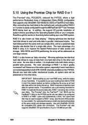
... both ATA-133 IDE channels available on your hard disks. a third, "hot" spare hard disk may be lost during boot up two or more detail). For optimal performance, install only identical hard disks of data access and storage. Read through the MBFastTrak133™ "Lite" firmware BIOS during the set up . It is possible to use a pre-existing hard disk for RAID 0 only if the data is to support a RAID 1 array; (see...
... both ATA-133 IDE channels available on your hard disks. a third, "hot" spare hard disk may be lost during boot up two or more detail). For optimal performance, install only identical hard disks of data access and storage. Read through the MBFastTrak133™ "Lite" firmware BIOS during the set up . It is possible to use a pre-existing hard disk for RAID 0 only if the data is to support a RAID 1 array; (see...
P4T533 User Manual
Page 129
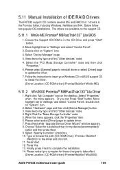
... "Start" button. Select the "PCI Mass Storage Controller" node and then click "Properties." 6. Please select [General] page to reinstall driver or select [Driver] page to take effect. (Driver Location: {CD-ROM driver}:\Promise\Raid0or1\Win2000) ASUS P4T533 motherboard user guide 109 Follow the instruction to insert your Windows CD or ASUS support CD to "Settings" and select "Control Panel". 3. Double click on the desktop. Press Next while "Upgrade Device Driver Wizard" window appears. 8. Move highlight bar to install the driver. (Driver Location...
... "Start" button. Select the "PCI Mass Storage Controller" node and then click "Properties." 6. Please select [General] page to reinstall driver or select [Driver] page to take effect. (Driver Location: {CD-ROM driver}:\Promise\Raid0or1\Win2000) ASUS P4T533 motherboard user guide 109 Follow the instruction to insert your Windows CD or ASUS support CD to "Settings" and select "Control Panel". 3. Double click on the desktop. Press Next while "Upgrade Device Driver Wizard" window appears. 8. Move highlight bar to install the driver. (Driver Location...
P4T533 User Manual
Page 133
... loading 81 Setup Program 56 Smart BIOS 2 Sub-menu launching 58 Updating 51 BIOS Beep Codes 47 Boot Device Selection 78 Boot Up NumLock Status 64 Boot Virus Detection 79 C C-Media Audio Setup 100 Central Processing Unit (CPU) 11 External Frequency 23 installation 12 Speed 66 Chip Configuration 68 Clear RTC RAM 29 Connectors Floppy Disk Drive 9 Smart Card Reader 10 CPU external freq. jumper 23 D DDR Voltage Setting 9, 24 Digital audio interfaces S/PDIF 6 DIP Switches 22 E Expansion card installation 19 IRQ assigments 20 Expansion slots 19 F Floppy 3 Mode 59 Floppy Disk Drive Connector 9 H Hard...
... loading 81 Setup Program 56 Smart BIOS 2 Sub-menu launching 58 Updating 51 BIOS Beep Codes 47 Boot Device Selection 78 Boot Up NumLock Status 64 Boot Virus Detection 79 C C-Media Audio Setup 100 Central Processing Unit (CPU) 11 External Frequency 23 installation 12 Speed 66 Chip Configuration 68 Clear RTC RAM 29 Connectors Floppy Disk Drive 9 Smart Card Reader 10 CPU external freq. jumper 23 D DDR Voltage Setting 9, 24 Digital audio interfaces S/PDIF 6 DIP Switches 22 E Expansion card installation 19 IRQ assigments 20 Expansion slots 19 F Floppy 3 Mode 59 Floppy Disk Drive Connector 9 H Hard...


