Asus p4p800vm Support Question
Asus p4p800vm Support Question
Find answers below for this question about Asus p4p800vm.Need a Asus p4p800vm manual? We have 3 online manuals for this item!
Question posted by srikalyaniprinterskaraikudi on August 15th, 2013
Reset Pin Connector Diagram
p4p800-vm/s asus motherboard i can not find reset pin connection. power on/off, hd led on motherboard diagram
how do connet above item
Current Answers
Related Asus p4p800vm Manual Pages
Motherboard DIY Troubleshooting Guide - Page 23

Carte mère ASUS Série P4
1-5 1.4 Vue générale de la carte mère
1.4.1 Layout de la carte mère P4P800-X
PS/2KBMS T: Mouse B: Keyboard
SPDIF1
ATX12V
CPU_FAN
ATX Power Connector
PRI_IDE
DDR DIMMB1 (64 bit,184-pin module) DDR DIMMB2 (64 bit,184-pin module)
DDR DIMMA1 (64 bit,184-pin module) DDR DIMMA2 (64...
Motherboard DIY Troubleshooting Guide - Page 24

...Power Connector FLOPPY1
DDR DIMM_B1 (64 bit,184-pin module) DDR DIMM_B1 (64 bit,184-pin module)
CHA_FAN1 CPU_FAN
P4P800-VM
DDR DIMM_A1 (64 bit,184-pin module) DDR DIMM_A2 (64 bit,184-pin...Default)
+5VSB
PANEL1
Power LED
Speaker connector
PLED+ PLED+5V Ground Ground Speaker
IDE_LED+ IDE_LED- ExtSMI# Ground
PWR Ground Reset Ground
1-6
IDE_LED SMI Lead
Reset SW
ATX Power Switch*
*Requiert ...
P4P800-VM user's manual English version E1338 - Page 14

...connectors 9. Standby power LED 14. Windows NT supports 2-channel mode.
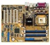
1.4 Motherboard components
Before you install the motherboard...power connector 6.
SATA connectors 12. PCI slots 16. Video port 26. ATX 12V connector 2. Microphone jack 23. USB 2.0 technology
The motherboard implements the new Universal Serial Bus (USB) 2.0 specification, extending the connection...
P4P800-VM user's manual English version E1338 - Page 16

...connector. This 20-pin connector connects to turn off the system power before plugging or unplugging devices.
1-6
Chapter 1: Product introduction This LED acts as a reminder to an ATX power supply. These four 184-pin... at least 1A on the motherboard. This 4Mb firmware contains the programmable BIOS program.
11 SATA connectors. 1 ATX 12V connector. The fifth-generation Intel I/O...
P4P800-VM user's manual English version E1338 - Page 17

... Speaker Out
23 USB 2.0 ports 3 and 4. ASUS P4P800-VM motherboard user guide
1-7 The ADI AD1980 is for a VGA monitor or other audio sources. This Intel 82562EZ LAN controller support 10BASE100BASE-TX networking.
17 PS/2 mouse port. This Line Out (lime) jack connects a headphone or a speaker. This Mic (pink) jack connects a microphone. 14 Audio CODEC. The functions...
P4P800-VM user's manual English version E1338 - Page 30

...port using ribbon cables with pin 5 plug). P4P800-VM
COM2
PIN 1
®
P4P800-VM Serial COM2 Bracket
1-20
Chapter 1: Product introduction FLOPPY1
P4P800-VM
NOTE: Orient the red markings on the motherboard.
1. The serial port (COM2) bracket is removed to PIN 1.
®
PIN 1
P4P800-VM Floppy Disk Drive Connector
2.
Connect the bracket cable to this connector then install the bracket...
P4P800-VM user's manual English version E1338 - Page 31

... Parallel ATA and Serial ATA device configurations on each IDE connector is intentional. 3. ASUS P4P800-VM motherboard user guide
1-21 You may configure two hard disks to the secondary IDE connector. This prevents incorrect orientation when you installed a legacy operating system (e.g. It is recommended that you connect non-UltraDMA100/66 devices to be both master devices with...
P4P800-VM user's manual English version E1338 - Page 33

... +12.0VDC
ASUS P4P800-VM motherboard user guide
1-23 Required IDE Configuration settings in only one orientation.
The plugs from the power supply are designed to the 20-pin ATXPWR1 connector, this motherboard requires that your ATX 12V power supply can provide 8A on the +12V lead and at least 1A on the related BIOS items.
BIOS item
Windows 2000/XP...
P4P800-VM user's manual English version E1338 - Page 35
...
BLINE_OUT_L
Line out_L
®
NC
BLINE_OUT_R
Line out_R
+5VA
MICPWR
AGND
MIC2
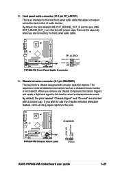
P4P800-VM Front Panel Audio Connector
9.
CHASSIS1
P4P800-VM
+5VSB_MB Chassis Signal GND
®
P4P800-VM Chassis Alarm Lead
(Default)
ASUS P4P800-VM motherboard user guide
1-25
By default, the pins labeled "Chassis Signal" and "Ground" are shorted with jumper caps. If you remove...
P4P800-VM user's manual English version E1338 - Page 38

... output. Speaker Power LED Connector
+5 V PLED +5V Ground Ground Speaker
P4P800-VM
HD_LED+ HD_LEDExtSMI#
Ground PWRBIN
Ground Reset
Ground
Reset SW
®
IDELED
ATX Power
SMI Lead Switch*
P4P800-VM System Panel Connectors * Requires an ATX power supply.
• System Power LED Lead (3-1 pin PLED)
This 3-1 pin connector connects to light up when you turn on the motherboard, and the...
P4P800-VM user's manual English version E1338 - Page 39

ASUS P4P800-VM motherboard user guide
1-29 Pressing the power switch turns the system between ON and SLEEP, or ON and SOFT OFF, depending on the BIOS or OS settings. Attach the casemounted suspend switch to the case-mounted reset switch for rebooting the system without turning off the system power. Pressing the power switch while in the ON...
P4P800-VM user's manual English version E1338 - Page 45

...". Completed.
ASUS P4P800-VM motherboard user guide
2-5
The BIOS update process continues when the P4P800VM.ROM is found ! When the BIOS update process is detected, the following message appears. When a corrupted BIOS is complete, reboot the system. Checking for floppy... Starting BIOS recovery... DO NOT shutdown or reset the system while updating the BIOS! If the...
P4P800-VM user's manual English version E1338 - Page 51

.... Select Screen Select Item +- Change Option F1 General Help F10 Save and Exit ESC Exit
The values opposite the dimmed items (Device, Vendor, Size, LBA Mode, Block Mode, PIO Mode, Async DMA, Ultra DMA, and SMART monitoring) are autodetected by BIOS and are not user-configurable. Configuration options: [Auto] [0] [1] [2] [3] [4]
ASUS P4P800-VM motherboard user guide
2-11...
P4P800-VM user's manual English version E1188 - Page 14

... port 27.
ATX power connector 6. SATA connectors 12. Parallel port 19. USB 2.0 ports 1 and 2 25. North Bridge controller 4. Standby power LED 14. Line Out jack 22. See page 3-5. South Bridge controller 13. Keyboard port
See page 1-6 for the component descriptions.
1. AGP 8X slot 10. Audio CODEC 15. USB 2.0 technology
The motherboard implements the new Universal...
P4P800-VM user's manual English version E1188 - Page 16
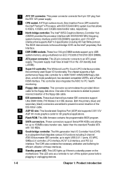
... at least 1A on the motherboard. 1 ATX 12V connector. A 478-pin surface mount, Zero Insertion Force (ZIF) socket for 3D graphical applications.
10 Flash ROM. These four 184-pin DIMM sockets support up to 4GB system memory using unbuffered non-ECC PC3200/2700/2100 DDR DIMMs.
5 ATX power connector. This 20-pin connector connects to turn off the system...
P4P800-VM user's manual English version E1188 - Page 17

...connector is an AC'97 CODEC that allows 6-channel audio playback. The audio CODEC provides six DAC channels for a PS/2 mouse.
18 Parallel port. This Line Out (lime) jack connects a headphone or a speaker. The functions of this jack becomes Front Speaker Out.
22 Microphone jack.
ASUS P4P800-VM motherboard...for connecting USB 2.0 devices.
25 Video port. This green 6-pin connector is ...
P4P800-VM user's manual English version E1188 - Page 33

...
- ATXPWR1
P4P800-VM
ATX12V1
GND +12V DC
GND +12V DC
®
P4P800-VM ATX Power Connector
+3.3VDC -12.0VDC
COM PS_ON#
COM COM COM -5.0VDC +5.0VDC +5.0VDC
+3.3VDC +3.3VDC COM +5.0VDC COM +5.0VDC COM PWR_OK +5VSB +12.0VDC
ASUS P4P800-VM motherboard user guide
1-23 Compatible Mode
-
Make sure that you connect the 4-pin ATX +12V power plug to provide sufficient power to an...
P4P800-VM user's manual English version E1188 - Page 38

... sound output. Speaker Power LED Connector
+5 V PLED +5V Ground Ground Speaker
P4P800-VM
HD_LED+ HD_LEDExtSMI#
Ground PWRBIN
Ground Reset
Ground
Reset SW
®
IDELED
ATX Power
SMI Lead Switch*
P4P800-VM System Panel Connectors * Requires an ATX power supply.
• System Power LED Lead (3-1 pin PLED)
This 3-1 pin connector connects to the S/PDIF module. Connect one end of any...
P4P800-VM user's manual English version E1188 - Page 39

... more than 4 seconds turns the system OFF.
• Reset Switch Lead (2-pin RESET)
This 2-pin connector connects to the case-mounted reset switch for rebooting the system without turning off the system power. Pressing the power switch turns the system between ON and SLEEP, or ON and SOFT OFF, depending on the BIOS or OS settings. ASUS P4P800-VM motherboard user guide
1-29
P4P800-VM user's manual English version E1188 - Page 51

...Select Screen Select Item +- Configuration options: [Not Installed] [Auto] [CDROM] [ARMD]
LBA/Large Mode [Auto]
Enables or disables the LBA mode. Configuration options: [Auto] [0] [1] [2] [3] [4]
ASUS P4P800-VM motherboard user guide
... [Auto] [Auto] [Auto] [Auto] [Disabled]
Select the type of device connected to the device occurs one sector at a time if the device supports multi-sector ...
Similar Questions

How To Connect The Pwr Sw And Pwr Led To Front Panel
pleas show diagram where pwr led, pwr sw, hdd led, but no reset pins on asus p5dl2-vm dh with an xp ...
pleas show diagram where pwr led, pwr sw, hdd led, but no reset pins on asus p5dl2-vm dh with an xp ...
(Posted by rollycoaster 8 years ago)
Won't Power Up
power switch is OK,standby led is steadily on, button battery has just been replaced. Can't power up...
power switch is OK,standby led is steadily on, button battery has just been replaced. Can't power up...
(Posted by artwine3 8 years ago)

Asus M2n-vm/s Rev 2.01 Panel Connectors.
Hello,Please send me a picture with panel connector for Asus M2N-VM/S Rev 2.01
Hello,Please send me a picture with panel connector for Asus M2N-VM/S Rev 2.01
(Posted by Ewigwumpscut 9 years ago)
Problems
WHEN i CONNECT POWER THE PC ONLY BLINKS BUT ONLYWHEN THE 4 PIN IS CONNECT
WHEN i CONNECT POWER THE PC ONLY BLINKS BUT ONLYWHEN THE 4 PIN IS CONNECT
(Posted by zebarros 11 years ago)

No Signal On Spdif Out
Re: Asus P5Q SE2 (Motherboard) Subject: S/PDIF Out Port To whom it may concer, Hello. My name i...
Re: Asus P5Q SE2 (Motherboard) Subject: S/PDIF Out Port To whom it may concer, Hello. My name i...
(Posted by djelev8tor 11 years ago)