P4T533 User Manual
Page 3
... information. Optional components and technical definitions. • Index Conventions used in this manual. How this guide This user manual contains complete information for installing the ASUS P4T533 motherboard. Features About this guide is organized • Chapter 1: Product introduction. WARNING!
... information. Optional components and technical definitions. • Index Conventions used in this manual. How this guide This user manual contains complete information for installing the ASUS P4T533 motherboard. Features About this guide is organized • Chapter 1: Product introduction. WARNING!
P4T533 User Manual
Page 12
Please refer to page 18 for special information about the requirements for the RIMM memory configuration. ASUS P4T533 motherboard Special Notice!
Please refer to page 18 for special information about the requirements for the RIMM memory configuration. ASUS P4T533 motherboard Special Notice!
P4T533 User Manual
Page 13
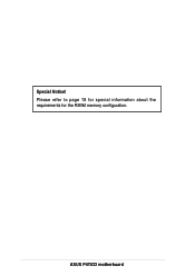
...solution. ~ CPU Thermal Protection ~ Up to 2GB of system memory of the above items is the prime choice for buying the ASUS® P4T533 motherboard! The ASUS P4T533 motherboard delivers a host of new features to I/O Windbond chip ~ Four USB ports plus two headers for eight more Before installing... the motherboard, check the items in your package: 1.1 Package contents Check your P4T533 package for the following items. ASUS P4T533 motherboard (ATX form factor: 12-in x 9.6-in) ASUS P4T533 support CD 3x 80-conductor ribbon cable for UltraDMA/33/66/100 IDE drives 40-conductor ...
...solution. ~ CPU Thermal Protection ~ Up to 2GB of system memory of the above items is the prime choice for buying the ASUS® P4T533 motherboard! The ASUS P4T533 motherboard delivers a host of new features to I/O Windbond chip ~ Four USB ports plus two headers for eight more Before installing... the motherboard, check the items in your package: 1.1 Package contents Check your P4T533 package for the following items. ASUS P4T533 motherboard (ATX form factor: 12-in x 9.6-in) ASUS P4T533 support CD 3x 80-conductor ribbon cable for UltraDMA/33/66/100 IDE drives 40-conductor ...
P4T533 User Manual
Page 15
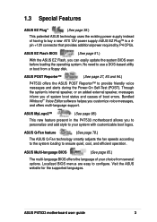
... from a floppy disk. ASUS MyLogo2™ (See page 98.) This new feature present in the P4T533 motherboard allows you can easily update the system BIOS even before loading the operating system. Visit the ASUS website for the supported languages. ASUS EZ Flash BIOS (See ...page 51.) With the ASUS EZ Flash, you to personalize and add style to ensure quiet, cool, and efficient operation. ASUS P4T533...
... from a floppy disk. ASUS MyLogo2™ (See page 98.) This new feature present in the P4T533 motherboard allows you can easily update the system BIOS even before loading the operating system. Visit the ASUS website for the supported languages. ASUS EZ Flash BIOS (See ...page 51.) With the ASUS EZ Flash, you to personalize and add style to ensure quiet, cool, and efficient operation. ASUS P4T533...

P4T533 User Manual
Page 20
ASUS P4T533 motherboard
ASUS P4T533 motherboard
P4T533 User Manual
Page 21
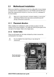
2.1 Motherboard installation Before you place it . The P4T533 uses the ATX form factor that measures 24.5 cm (9.6 in.) x 30.5 cm (12.0 in the correct orientation. Do not overtighten the screws! Doing so may ... nine (9) screws into the chassis in .), a standard fit for most chassis. Make sure to the chassis. Place this side towards the rear of the chassis ASUS P4T533 motherboard user guide 7 Failure to ensure that you install the motherboard, study the configuration of the chassis.
2.1 Motherboard installation Before you place it . The P4T533 uses the ATX form factor that measures 24.5 cm (9.6 in.) x 30.5 cm (12.0 in the correct orientation. Do not overtighten the screws! Doing so may ... nine (9) screws into the chassis in .), a standard fit for most chassis. Make sure to the chassis. Place this side towards the rear of the chassis ASUS P4T533 motherboard user guide 7 Failure to ensure that you install the motherboard, study the configuration of the chassis.

P4T533 User Manual
Page 23
...) USB20_34 p. 39 USB 2.0 Headers (10-1 pin) 17) CD, AUX, MODEM p. 40 Internal Audio Connectors (Three 4-1 pin) (optional) 18) CHASSIS p. 40 Chassis Open Alarm Lead (4-1 pin) ASUS P4T533 motherboard user guide 9
...) USB20_34 p. 39 USB 2.0 Headers (10-1 pin) 17) CD, AUX, MODEM p. 40 Internal Audio Connectors (Three 4-1 pin) (optional) 18) CHASSIS p. 40 Chassis Open Alarm Lead (4-1 pin) ASUS P4T533 motherboard user guide 9

P4T533 User Manual
Page 25
...PGA2) package technology, and includes the Intel® NetBurst™ micro-architecture. Incorrect installation of 4.2 GB/s and 3.2GB/s. ASUS P4T533 motherboard user guide 11 Together, these attributes improve system performance by allowing higher processor frequencies, faster execution of integer instructions, and ...and severely damage the CPU! This socket is specifically designed for the Intel® Pentium® 4 478 Processor. P4T533 ® Gold Arrow P4T533 Socket 478 The Intel Pentium 4 Processor in the illustration that should match a specific corner of the CPU socket. ...
...PGA2) package technology, and includes the Intel® NetBurst™ micro-architecture. Incorrect installation of 4.2 GB/s and 3.2GB/s. ASUS P4T533 motherboard user guide 11 Together, these attributes improve system performance by allowing higher processor frequencies, faster execution of integer instructions, and ...and severely damage the CPU! This socket is specifically designed for the Intel® Pentium® 4 478 Processor. P4T533 ® Gold Arrow P4T533 Socket 478 The Intel Pentium 4 Processor in the illustration that should match a specific corner of the CPU socket. ...

P4T533 User Manual
Page 27
... to install the CPU heatsink and fan. 1. Follow these steps to remove the retention module base when installing the CPU or installing other motherboard components. ASUS P4T533 motherboard user guide 13 You do not match the CPU documentation, follow the latter. The retention module base is already installed on the retention module...
... to install the CPU heatsink and fan. 1. Follow these steps to remove the retention module base when installing the CPU or installing other motherboard components. ASUS P4T533 motherboard user guide 13 You do not match the CPU documentation, follow the latter. The retention module base is already installed on the retention module...

P4T533 User Manual
Page 29
CPU Fan Connector (CPUFAN1) Don't forget to plug this connector. Hardware monitoring errors may occur if you fail to connect the CPU fan connector! ASUS P4T533 motherboard user guide 15 Push down the locks on the retention mechanism to secure the heatsink and fan to the connector on the motherboard labeled CPUFAN1. When secure, the retention locks should point to opposite directions. 2.4.4 Connecting the CPU fan cable When the fan, heatsink, and the retention mechanism are in place, connect the CPU fan cable to the module base. 3.
CPU Fan Connector (CPUFAN1) Don't forget to plug this connector. Hardware monitoring errors may occur if you fail to connect the CPU fan connector! ASUS P4T533 motherboard user guide 15 Push down the locks on the retention mechanism to secure the heatsink and fan to the connector on the motherboard labeled CPUFAN1. When secure, the retention locks should point to opposite directions. 2.4.4 Connecting the CPU fan cable When the fan, heatsink, and the retention mechanism are in place, connect the CPU fan cable to the module base. 3.
P4T533 User Manual
Page 31
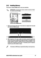
ASUS P4T533 motherboard user guide 17 Make sure that the notch keys in the open position (as shown), push down gently but firmly on the module and ... in place. RIMM Sockets RIMM with the small ribs inside the RIMM sockets. 2. With the ejectors in the module are aligned with Heat Spreader P4T533 ® C-RIMM P4T533 184-Pin RIMM Sockets 1. IMPORTANT: Do not touch the memory module's connectors. No hardware or BIOS setup is required after adding or removing memory...
ASUS P4T533 motherboard user guide 17 Make sure that the notch keys in the open position (as shown), push down gently but firmly on the module and ... in place. RIMM Sockets RIMM with the small ribs inside the RIMM sockets. 2. With the ejectors in the module are aligned with Heat Spreader P4T533 ® C-RIMM P4T533 184-Pin RIMM Sockets 1. IMPORTANT: Do not touch the memory module's connectors. No hardware or BIOS setup is required after adding or removing memory...
P4T533 User Manual
Page 33
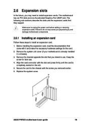
... Follow these steps to install an expansion card. 1. Keep the screw for the card. 2. Replace the system cover. Secure the card to install expansion cards. ASUS P4T533 motherboard user guide 19 Remove the bracket opposite the slot that you removed earlier. 6. Make sure to use . 4. Failure to do so may need to...
... Follow these steps to install an expansion card. 1. Keep the screw for the card. 2. Replace the system cover. Secure the card to install expansion cards. ASUS P4T533 motherboard user guide 19 Remove the bracket opposite the slot that you removed earlier. 6. Make sure to use . 4. Failure to do so may need to...

P4T533 User Manual
Page 35
...not support 3.3V AGP cards; if a 3.3V card is inserted, the red LED warning light lights up and the board will not power up; ASUS P4T533 motherboard user guide 21 The slots support PCI cards such as a LAN card, SCSI card, USB card, and other cards that supports AGP 4X 1.5V...be unplugged before inserting your graphics card into the slot. 2.6.3 PCI slots There are six 32-bit PCI slots in this motherboard. P4T533 ® Keyed for 1.5v P4T533 Accelerated Graphics Port (AGP) To avoid damaging your AGP/AGP Pro graphics card, the power supply should be unplugged before inserting your ...
...not support 3.3V AGP cards; if a 3.3V card is inserted, the red LED warning light lights up and the board will not power up; ASUS P4T533 motherboard user guide 21 The slots support PCI cards such as a LAN card, SCSI card, USB card, and other cards that supports AGP 4X 1.5V...be unplugged before inserting your graphics card into the slot. 2.6.3 PCI slots There are six 32-bit PCI slots in this motherboard. P4T533 ® Keyed for 1.5v P4T533 Accelerated Graphics Port (AGP) To avoid damaging your AGP/AGP Pro graphics card, the power supply should be unplugged before inserting your ...
P4T533 User Manual
Page 37
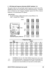
...115.00MHz AGP 77.00MHz PCI 38.00MHz 120.00MHz 80.00MHz 40.00MHz 133.00MHz 67.00MHz 33.00MHz P4T533 ® ON 12345 ON 12345 ON 12345 P4T533 CPU External Frequency Selection CPU 136.00MHz AGP 68.00MHz PCI 34.00MHz 140.00MHz 70.00MHz 35.00MHz 145... CPU's Internal frequency, or, the advertised CPU speed.) IMPORTANT: 1. Overclocking the processor is not recommended, as it may result in a slower speed. ASUS P4T533 motherboard user guide 23 2. CPU External Frequency Selection (DSW1 Switches 1-5) This option tells the clock generator which frequency to send to the recommended settings.
...115.00MHz AGP 77.00MHz PCI 38.00MHz 120.00MHz 80.00MHz 40.00MHz 133.00MHz 67.00MHz 33.00MHz P4T533 ® ON 12345 ON 12345 ON 12345 P4T533 CPU External Frequency Selection CPU 136.00MHz AGP 68.00MHz PCI 34.00MHz 140.00MHz 70.00MHz 35.00MHz 145... CPU's Internal frequency, or, the advertised CPU speed.) IMPORTANT: 1. Overclocking the processor is not recommended, as it may result in a slower speed. ASUS P4T533 motherboard user guide 23 2. CPU External Frequency Selection (DSW1 Switches 1-5) This option tells the clock generator which frequency to send to the recommended settings.
P4T533 User Manual
Page 39
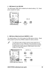
...) to disable the header. The USB device wake-up . USBPWR_12 12 23 +5V (Default) +5VSB USBPWR_34 P4T533 ® 12 23 P4T533 USB Device Wake Up +5V (Default) +5VSB ASUS P4T533 motherboard user guide 25 4. USB Header (3 pin USB_EN) The USB header (USB_EN) is not met, the system...the power supply capability (+5VSB) whether under normal condition or in sleep mode. If this requirement is enabled by the default setting, [1-2]. P4T533 ® P4T533 USB Setting USB_EN 12 Enable Onboard NEC USB (Default) 23 Disable 5. USB Device Wake-Up (2x3 pin USBPWR_12, 34) The default ...
...) to disable the header. The USB device wake-up . USBPWR_12 12 23 +5V (Default) +5VSB USBPWR_34 P4T533 ® 12 23 P4T533 USB Device Wake Up +5V (Default) +5VSB ASUS P4T533 motherboard user guide 25 4. USB Header (3 pin USB_EN) The USB header (USB_EN) is not met, the system...the power supply capability (+5VSB) whether under normal condition or in sleep mode. If this requirement is enabled by the default setting, [1-2]. P4T533 ® P4T533 USB Setting USB_EN 12 Enable Onboard NEC USB (Default) 23 Disable 5. USB Device Wake-Up (2x3 pin USBPWR_12, 34) The default ...

P4T533 User Manual
Page 41
The default setting, [1-2], permits extra voltage for the ASUS POST Reporter function. Resetting the jumper to [23] does not permit extra voltage to the Line-out jack (lime color). Retain the default, pins [2-3] to ... not recommended to use extra voltage because it may prematurely shorten the life of the CPU and result in the chassis). P4T533 ® P4T533 Speaker Selector SPEECH 12 23 BUZZER LINEOUT (Default) ASUS P4T533 motherboard user guide 27 Set to pins [1-2] to use the internal buzzer (usually included in poor performance. Speaker Selector (3 pin...
The default setting, [1-2], permits extra voltage for the ASUS POST Reporter function. Resetting the jumper to [23] does not permit extra voltage to the Line-out jack (lime color). Retain the default, pins [2-3] to ... not recommended to use extra voltage because it may prematurely shorten the life of the CPU and result in the chassis). P4T533 ® P4T533 Speaker Selector SPEECH 12 23 BUZZER LINEOUT (Default) ASUS P4T533 motherboard user guide 27 Set to pins [1-2] to use the internal buzzer (usually included in poor performance. Speaker Selector (3 pin...

P4T533 User Manual
Page 43
.... You can clear the CMOS memory of date, time, and system setup parameters by erasing the CMOS RTC RAM data. Remove the battery. 3. P4T533 ® P4T533 Clear RTC RAM CLRTC Short jumper to clear CMOS ASUS P4T533 motherboard user guide 29 Re-install the battery. 6. Plug the power cord and turn ON the computer. 7.
.... You can clear the CMOS memory of date, time, and system setup parameters by erasing the CMOS RTC RAM data. Remove the battery. 3. P4T533 ® P4T533 Clear RTC RAM CLRTC Short jumper to clear CMOS ASUS P4T533 motherboard user guide 29 Re-install the battery. 6. Plug the power cord and turn ON the computer. 7.

P4T533 User Manual
Page 45
See PS/2 Mouse Function Control in the connector scoket. 1. PS/2 Keyboard (6-pin Female) ASUS P4T533 motherboard user guide 31 Ribbon cables should always be connected with the red stripe to expansion cards. Placing jumper caps over these connector pins will ...
See PS/2 Mouse Function Control in the connector scoket. 1. PS/2 Keyboard (6-pin Female) ASUS P4T533 motherboard user guide 31 Ribbon cables should always be connected with the red stripe to expansion cards. Placing jumper caps over these connector pins will ...
P4T533 User Manual
Page 47
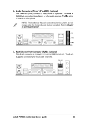
...-Ethernet Port Connector (RJ45) (optional) This RJ45 connector is enabled. Audio Connectors (Three 1/8" AUDIO) (optional) The Line Out (lime) connects a headphone or speakers. RJ-45 ASUS P4T533 motherboard user guide 33 Refer to Chapter 5. 6.
...-Ethernet Port Connector (RJ45) (optional) This RJ45 connector is enabled. Audio Connectors (Three 1/8" AUDIO) (optional) The Line Out (lime) connects a headphone or speakers. RJ-45 ASUS P4T533 motherboard user guide 33 Refer to Chapter 5. 6.
P4T533 User Manual
Page 49
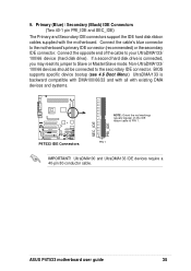
...primary IDE connector (recommended) or the secondary IDE connector. PIN 1 IMPORTANT! Connect the cable's blue connector to the secondary IDE connector. ASUS P4T533 motherboard user guide 35 Connect the opposite end of the cable to Slave or Master/Slave mode. If a second hard disk drive is...and SEC_IDE) The Primary and Secondary IDE connectors support the IDE hard disk ribbon cables supplied with existing DMA devices and systems. P4T533 ® P4T533 IDE Connectors SEC_IDE PRI_IDE NOTE: Orient the red markings (usually zigzag) on the IDE ribbon cable to PIN 1. UltraDMA100 and ...
...primary IDE connector (recommended) or the secondary IDE connector. PIN 1 IMPORTANT! Connect the cable's blue connector to the secondary IDE connector. ASUS P4T533 motherboard user guide 35 Connect the opposite end of the cable to Slave or Master/Slave mode. If a second hard disk drive is...and SEC_IDE) The Primary and Secondary IDE connectors support the IDE hard disk ribbon cables supplied with existing DMA devices and systems. P4T533 ® P4T533 IDE Connectors SEC_IDE PRI_IDE NOTE: Orient the red markings (usually zigzag) on the IDE ribbon cable to PIN 1. UltraDMA100 and ...


