P4T533 User Manual
Page 4
... this guide iii How this guide is organized iii Conventions used in this guide iii Safety information vi FCC/CDC statements vii ASUS contact information viii P4T533 specifications summary ix Chapter 1: Product introduction 1 Welcome 1 1.1 Package contents 1 1.2 Core Specifications 2 1.3 Special Features 3 ... 12 2.4.3 Installing the heatsink and fan 13 2.4.4 Connecting the CPU fan cable 15 2.5 System memory 16 2.5.1 Overview 16 2.5.2 Installing Memory 17 2.5.3 Removing Memory 18 2.5.4 General RIMM Memos 18 2.6 Expansion slots 19 2.6.1 Installing an expansion card 19 2.6.2 ...
... this guide iii How this guide is organized iii Conventions used in this guide iii Safety information vi FCC/CDC statements vii ASUS contact information viii P4T533 specifications summary ix Chapter 1: Product introduction 1 Welcome 1 1.1 Package contents 1 1.2 Core Specifications 2 1.3 Special Features 3 ... 12 2.4.3 Installing the heatsink and fan 13 2.4.4 Connecting the CPU fan cable 15 2.5 System memory 16 2.5.1 Overview 16 2.5.2 Installing Memory 17 2.5.3 Removing Memory 18 2.5.4 General RIMM Memos 18 2.6 Expansion slots 19 2.6.1 Installing an expansion card 19 2.6.2 ...

P4T533 User Manual
Page 9
P4T533 specifications summary CPU Socket 478 for 2 additional USB ports CPU/Power/Chassis fan connectors...Promise® ATA133 / RAID 0/1 IDE controller Intel® 8256ET ethernet controller (optional) ASUS JumperFree™ mode ASUS POST Reporter™ ASUS EZ Plug™ ASUS EZ Flash ASUS MyLogo2™ ASUS Q-Fan ASUS Multi-language BIOS S/PDIF In/Out Module bundled (optional) Power Loss Restart Adjustable CPU...cache Chipset Intel 82850E MCH Intel 82801BA ICH2 (B4) Front Side Bus (FSB) 533 / 400 MHz Memory 2 x 232-pin 32-bit RIMM4200/3200-compliant Rambus DRAMs (RDRAMs) up to 2GB...
P4T533 specifications summary CPU Socket 478 for 2 additional USB ports CPU/Power/Chassis fan connectors...Promise® ATA133 / RAID 0/1 IDE controller Intel® 8256ET ethernet controller (optional) ASUS JumperFree™ mode ASUS POST Reporter™ ASUS EZ Plug™ ASUS EZ Flash ASUS MyLogo2™ ASUS Q-Fan ASUS Multi-language BIOS S/PDIF In/Out Module bundled (optional) Power Loss Restart Adjustable CPU...cache Chipset Intel 82850E MCH Intel 82801BA ICH2 (B4) Front Side Bus (FSB) 533 / 400 MHz Memory 2 x 232-pin 32-bit RIMM4200/3200-compliant Rambus DRAMs (RDRAMs) up to 2GB...
P4T533 User Manual
Page 12
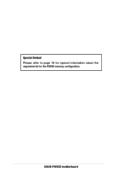
Please refer to page 18 for special information about the requirements for the RIMM memory configuration. ASUS P4T533 motherboard Special Notice!
Please refer to page 18 for special information about the requirements for the RIMM memory configuration. ASUS P4T533 motherboard Special Notice!
P4T533 User Manual
Page 13
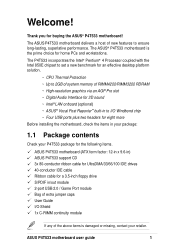
... solution. ~ CPU Thermal Protection ~ Up to 2GB of system memory of RIMM4200/RIMM3200 RDRAM ~ High-resolution graphics via an AGP Pro slot ~ Digital Audio Interface for 3D sound ~ Intel® LAN onboard (optional) ~ ASUS® Vocal Post Reporter™ built-in /out module 2-port...above items is the prime choice for buying the ASUS® P4T533 motherboard! The ASUS® P4T533 motherboard is damaged or missing, contact your P4T533 package for the following items. ASUS P4T533 motherboard (ATX form factor: 12-in x 9.6-in) ASUS P4T533 support CD 3x 80-conductor ribbon cable for UltraDMA...
... solution. ~ CPU Thermal Protection ~ Up to 2GB of system memory of RIMM4200/RIMM3200 RDRAM ~ High-resolution graphics via an AGP Pro slot ~ Digital Audio Interface for 3D sound ~ Intel® LAN onboard (optional) ~ ASUS® Vocal Post Reporter™ built-in /out module 2-port...above items is the prime choice for buying the ASUS® P4T533 motherboard! The ASUS® P4T533 motherboard is damaged or missing, contact your P4T533 package for the following items. ASUS P4T533 motherboard (ATX form factor: 12-in x 9.6-in) ASUS P4T533 support CD 3x 80-conductor ribbon cable for UltraDMA...
P4T533 User Manual
Page 14
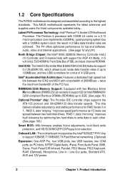
... Intel RIMM4200/ 3200-compliant Rambus DRAMs (RDRAMs) up to 100MB/sec; 1.2 Core Specifications The P4T533 motherboard is designed and assembled according to each other. (See page 100.) Smart BIOS: 4Mb ... video and Internet applications. (See page 12 and 24.) North Bridge Chipset: the Intel® 850E (82850E Memory Controller Hub,) I /O tasks are achieved. The P4 offers optimized performance for RAID levels 0 or 1. Onboard ...hub link between two hard disk drives. This ASUS motherboard represents the latest advances and supplies users the finest components available today...
... Intel RIMM4200/ 3200-compliant Rambus DRAMs (RDRAMs) up to 100MB/sec; 1.2 Core Specifications The P4T533 motherboard is designed and assembled according to each other. (See page 100.) Smart BIOS: 4Mb ... video and Internet applications. (See page 12 and 24.) North Bridge Chipset: the Intel® 850E (82850E Memory Controller Hub,) I /O tasks are achieved. The P4 offers optimized performance for RAID levels 0 or 1. Onboard ...hub link between two hard disk drives. This ASUS motherboard represents the latest advances and supplies users the finest components available today...

P4T533 User Manual
Page 16
1.4 Motherboard Components Before installing the P4T533 motherboard, take time to familiarize yourself with its configuration: understanding the motherboard makes upgrading easy. Processor Support Chipsets Main Memory Expansion Slots Major System I/O Hardware Monitoring Special Feature Network Feature Audio Features Power ... Serial Ports (COM1/2 40 USB 1.1 Connectors (Port 1/2 41 PS/2 Keyboard Connector purple) 42 System Voltage Monitor (integrated in ASUS ASIC 11 Onboard LED 24 Onboard AGP Warning LED 7 Modem Connector 29 RJ45 Connector (optional 35 (Audio Models Only) S/PDIF Connector...
1.4 Motherboard Components Before installing the P4T533 motherboard, take time to familiarize yourself with its configuration: understanding the motherboard makes upgrading easy. Processor Support Chipsets Main Memory Expansion Slots Major System I/O Hardware Monitoring Special Feature Network Feature Audio Features Power ... Serial Ports (COM1/2 40 USB 1.1 Connectors (Port 1/2 41 PS/2 Keyboard Connector purple) 42 System Voltage Monitor (integrated in ASUS ASIC 11 Onboard LED 24 Onboard AGP Warning LED 7 Modem Connector 29 RJ45 Connector (optional 35 (Audio Models Only) S/PDIF Connector...
P4T533 User Manual
Page 18
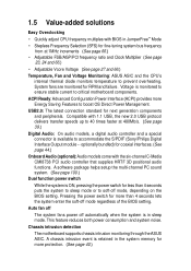
...retained in sleep mode. Voltage is monitored to ensure stable current to soft-off automatically when the system is in the system memory for more Energy Saving Features to boost OS Direct Power Management. Pressing the power switch for more protection. (See page 40....) Chassis intrusion detection The motherboard supports chassis intrusion monitoring through the ASUS ASIC. ACPI Ready: Advanced Configuration Power Interface (ACPI) provides more than 4 seconds puts the system to sleep mode or to critical...
...retained in sleep mode. Voltage is monitored to ensure stable current to soft-off automatically when the system is in the system memory for more Energy Saving Features to boost OS Direct Power Management. Pressing the power switch for more protection. (See page 40....) Chassis intrusion detection The motherboard supports chassis intrusion monitoring through the ASUS ASIC. ACPI Ready: Advanced Configuration Power Interface (ACPI) provides more than 4 seconds puts the system to sleep mode or to critical...
P4T533 User Manual
Page 22
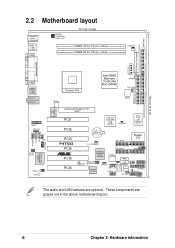
... LINE_IN LO_L LO_R BCS2 BCS1 SPDIF_C LED1 Intel LAN Controller Socket 478 Intel 850E Memory Controller Hub (MCH) TRPWR CPU_FAN ATX12V DSWF Accelerated Graphics Port AGP PCI1 Intel I/O Controller Hub (ICH2) CLCMOS ASUS ASIC with Hardware Monitor PCI2 PCI3 P4T533 PCI4 ® PCI5 PCI6 CR2032 3V Lithium Cell CMOS Power SEC_RAID Super I/O CH_FAN...
... LINE_IN LO_L LO_R BCS2 BCS1 SPDIF_C LED1 Intel LAN Controller Socket 478 Intel 850E Memory Controller Hub (MCH) TRPWR CPU_FAN ATX12V DSWF Accelerated Graphics Port AGP PCI1 Intel I/O Controller Hub (ICH2) CLCMOS ASUS ASIC with Hardware Monitor PCI2 PCI3 P4T533 PCI4 ® PCI5 PCI6 CR2032 3V Lithium Cell CMOS Power SEC_RAID Super I/O CH_FAN...

P4T533 User Manual
Page 23
... Expansion Slots 1) Socket 478 p. 12 Installing the CPU 2) Heatsink p. 13 Installing the Heatsink and Fan 3) Memory p. 16 System Memory Support 4) PCI 1/2/3/4/5/6 p. 19 32-bit PCI Bus Expansion Slots 5) AGP Pro p. 21 Accelerated Graphics Slot Motherboard Settings (Switches and Jumpers) 1) JEN p. 22 JumperFree Mode Setting (...) USB20_34 p. 39 USB 2.0 Headers (10-1 pin) 17) CD, AUX, MODEM p. 40 Internal Audio Connectors (Three 4-1 pin) (optional) 18) CHASSIS p. 40 Chassis Open Alarm Lead (4-1 pin) ASUS P4T533 motherboard user guide 9
... Expansion Slots 1) Socket 478 p. 12 Installing the CPU 2) Heatsink p. 13 Installing the Heatsink and Fan 3) Memory p. 16 System Memory Support 4) PCI 1/2/3/4/5/6 p. 19 32-bit PCI Bus Expansion Slots 5) AGP Pro p. 21 Accelerated Graphics Slot Motherboard Settings (Switches and Jumpers) 1) JEN p. 22 JumperFree Mode Setting (...) USB20_34 p. 39 USB 2.0 Headers (10-1 pin) 17) CD, AUX, MODEM p. 40 Internal Audio Connectors (Three 4-1 pin) (optional) 18) CHASSIS p. 40 Chassis Open Alarm Lead (4-1 pin) ASUS P4T533 motherboard user guide 9

P4T533 User Manual
Page 30
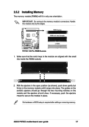
...must be used to avoid breaking the signal lines, which are a serial connection in the following sizes: 128, 256 and 512Mbit RDRAM RIMMs. Location Memory Module Subtotal RIMM1 (Rows 0&1) RDRAM x 1 and/or C-RIMM (Use when socket is unpopulated.) RIMM2 (Rows 2&3) RDRAM x 1 and/or... below shows the various combinations for inserting RIMMs.) a. These sockets support 32-bit RIMMs in a Rambus interface. 2.5 System memory 2.5.1 Overview This motherboard has two 232-pin Rambus Inline Memory Modules (RIMM) sockets. C-RIMM 128 / 256 / 512 MB RDRAM RIMM1 RIMM2 b. 128 / 256 / 512 MB...
...must be used to avoid breaking the signal lines, which are a serial connection in the following sizes: 128, 256 and 512Mbit RDRAM RIMMs. Location Memory Module Subtotal RIMM1 (Rows 0&1) RDRAM x 1 and/or C-RIMM (Use when socket is unpopulated.) RIMM2 (Rows 2&3) RDRAM x 1 and/or... below shows the various combinations for inserting RIMMs.) a. These sockets support 32-bit RIMMs in a Rambus interface. 2.5 System memory 2.5.1 Overview This motherboard has two 232-pin Rambus Inline Memory Modules (RIMM) sockets. C-RIMM 128 / 256 / 512 MB RDRAM RIMM1 RIMM2 b. 128 / 256 / 512 MB...
P4T533 User Manual
Page 31
...go through the two mounting notches on the memory module until it snaps into place. No hardware or BIOS setup is required after adding or removing memory. RIMM Sockets RIMM with the small ribs inside the RIMM sockets. 2. ASUS P4T533 motherboard user guide 17 IMPORTANT: Do not touch... the memory module's connectors. If necessary, push the ejectors inward to secure the ...
...go through the two mounting notches on the memory module until it snaps into place. No hardware or BIOS setup is required after adding or removing memory. RIMM Sockets RIMM with the small ribs inside the RIMM sockets. 2. ASUS P4T533 motherboard user guide 17 IMPORTANT: Do not touch... the memory module's connectors. If necessary, push the ejectors inward to secure the ...
P4T533 User Manual
Page 32
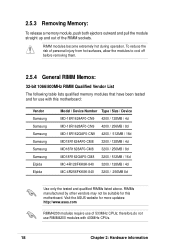
... information RIMM modules become extremely hot during operation. therefore,do not use of the RIMM sockets. Visit the ASUS website for more updates: http://www.asus.com RIMM4200 modules require use RIMM4200 modules with this motherboard. To reduce the risk of personal injury from hot... surfaces, allow the modules to cool off before removing them. 2.5.4 General RIMM Memos: 32-bit 1066/800MHz RIMM Qualified Vendor List The following table lists qualified memory...
... information RIMM modules become extremely hot during operation. therefore,do not use of the RIMM sockets. Visit the ASUS website for more updates: http://www.asus.com RIMM4200 modules require use RIMM4200 modules with this motherboard. To reduce the risk of personal injury from hot... surfaces, allow the modules to cool off before removing them. 2.5.4 General RIMM Memos: 32-bit 1066/800MHz RIMM Qualified Vendor List The following table lists qualified memory...

P4T533 User Manual
Page 43
The RAM data in CMOS. To erase the RTC RAM: 1. Remove the jumper cap. 5. You can clear the CMOS memory of date, time, and system setup parameters by the onboard button cell battery. Clear RTC RAM (2 pin CLRTC) This jumper allows you to re-enter ... the power cord. 2. Re-install the battery. 6. Plug the power cord and turn ON the computer. 7. Short the jumper by putting on the jumper cap. 4. P4T533 ® P4T533 Clear RTC RAM CLRTC Short jumper to clear CMOS ASUS P4T533 motherboard user guide 29
The RAM data in CMOS. To erase the RTC RAM: 1. Remove the jumper cap. 5. You can clear the CMOS memory of date, time, and system setup parameters by the onboard button cell battery. Clear RTC RAM (2 pin CLRTC) This jumper allows you to re-enter ... the power cord. 2. Re-install the battery. 6. Plug the power cord and turn ON the computer. 7. Short the jumper by putting on the jumper cap. 4. P4T533 ® P4T533 Clear RTC RAM CLRTC Short jumper to clear CMOS ASUS P4T533 motherboard user guide 29
P4T533 User Manual
Page 63
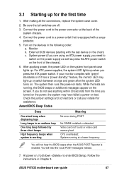
...power LED on tests. You will not hear the BIOS beeps when the ASUS POST Reporter is working Meaning No error during POST No DRAM installed or detected Video card not found or video card memory bad CPU overheated; System power (if you are running at the back of... the chassis). 6. Monitor b. 3.1 Starting up for assistance. After making all switches are off. 3. Connect the power cord to enter BIOS Setup. For ATX power supplies, the system LED lights up . ASUS P4T533 motherboard ...
...power LED on tests. You will not hear the BIOS beeps when the ASUS POST Reporter is working Meaning No error during POST No DRAM installed or detected Video card not found or video card memory bad CPU overheated; System power (if you are running at the back of... the chassis). 6. Monitor b. 3.1 Starting up for assistance. After making all switches are off. 3. Connect the power cord to enter BIOS Setup. For ATX power supplies, the system LED lights up . ASUS P4T533 motherboard ...
P4T533 User Manual
Page 64
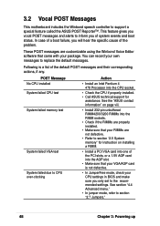
...See section "4.4 Advanced menu." • In jumper mode, refer to support a special feature called the ASUS POST Reporter™. This feature gives you vocal POST messages and alerts to section "2.5 System memory" for assistance. These POST messages are not defective. • Refer to inform you of the default ...the PCI slots, or a 1.5V AGP card into one of the problem. POST Message No CPU installed System failed CPU test System failed memory test System failed VGA test System failed due to CPU over-clocking Action • Install an Intel Pentium 4 478 Processor into the RIMM ...
...See section "4.4 Advanced menu." • In jumper mode, refer to support a special feature called the ASUS POST Reporter™. This feature gives you vocal POST messages and alerts to section "2.5 System memory" for assistance. These POST messages are not defective. • Refer to inform you of the default ...the PCI slots, or a 1.5V AGP card into one of the problem. POST Message No CPU installed System failed CPU test System failed memory test System failed VGA test System failed due to CPU over-clocking Action • Install an Intel Pentium 4 478 Processor into the RIMM ...
P4T533 User Manual
Page 70
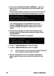
... the system with the update process. Flash Memory: SST 49LF004 1. Press any key to update the BIOS (Y/N)? _ If you typed. EZ Flash will automatically access drive A to remove the message, then type in File] BIOS Version: P4T533 Boot Block WARNING! appears. 5. When found... ." File not found , the following prompts appear if you downloaded from the ASUS website, then press . For item 2, "Update Boot Block area," press Y to...
... the system with the update process. Flash Memory: SST 49LF004 1. Press any key to update the BIOS (Y/N)? _ If you typed. EZ Flash will automatically access drive A to remove the message, then type in File] BIOS Version: P4T533 Boot Block WARNING! appears. 5. When found... ." File not found , the following prompts appear if you downloaded from the ASUS website, then press . For item 2, "Update Boot Block area," press Y to...
P4T533 User Manual
Page 71
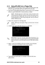
... is either not programmable or is recommended that may be programmed by the Flash Memory Writer utility. 5. The Save Current BIOS To File screen appears. 6. In DOS mode, type A:\AFLASH to the disk. 2. Select 1. ASUS P4T533 motherboard user guide 53 Type FORMAT A:/S at the DOS prompt to the boot disk ... to create a bootable system disk. NOTE! It does not function in the DOS prompt within Windows, and does not function with certain memory drivers that you created. NOTE! Use only a DOS 6.2, WIN95 / WIN98 boot disk. 3. 4.1.2 Using AFLASH from the hard drive.
... is either not programmable or is recommended that may be programmed by the Flash Memory Writer utility. 5. The Save Current BIOS To File screen appears. 6. In DOS mode, type A:\AFLASH to the disk. 2. Select 1. ASUS P4T533 motherboard user guide 53 Type FORMAT A:/S at the DOS prompt to the boot disk ... to create a bootable system disk. NOTE! It does not function in the DOS prompt within Windows, and does not function with certain memory drivers that you created. NOTE! Use only a DOS 6.2, WIN95 / WIN98 boot disk. 3. 4.1.2 Using AFLASH from the hard drive.

P4T533 User Manual
Page 73
... not able to the boot disk. 7. Follow the onscreen instructions to program the new BIOS information into the Flash ROM. If the Flash Memory Writer utility is done, the message "Flashed Successfully" appears. 8. If this may not boot. If you saved to successfully update a complete...file you encounter problems while updating the new BIOS, DO NOT turn off the system because this happens, call the ASUS service center for support. ASUS P4T533 motherboard user guide 55 The utility starts to continue. This minimizes the possibility of boot problems in case of update ...
... not able to the boot disk. 7. Follow the onscreen instructions to program the new BIOS information into the Flash ROM. If the Flash Memory Writer utility is done, the message "Flashed Successfully" appears. 8. If this may not boot. If you saved to successfully update a complete...file you encounter problems while updating the new BIOS, DO NOT turn off the system because this happens, call the ASUS service center for support. ASUS P4T533 motherboard user guide 55 The utility starts to continue. This minimizes the possibility of boot problems in case of update ...
P4T533 User Manual
Page 83
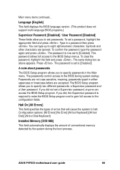
The same dialog box as above appears. Halt On [All Errors] This field specifies the types of conventional memory detected by the system during system startup. Language [English] This field displays the BIOS language version. (This product does not support...but Keyboard] [All but Disk] [All but Disk/Keyboard] Installed Memory [XXX MB] This field automatically displays the amount of errors that will cause the system to specify two different passwords: a Supervisor password and a User password. ASUS P4T533 motherboard user guide 65 Symbols and other characters are accepted. If ...
The same dialog box as above appears. Halt On [All Errors] This field specifies the types of conventional memory detected by the system during system startup. Language [English] This field displays the BIOS language version. (This product does not support...but Keyboard] [All but Disk] [All but Disk/Keyboard] Installed Memory [XXX MB] This field automatically displays the amount of errors that will cause the system to specify two different passwords: a Supervisor password and a User password. ASUS P4T533 motherboard user guide 65 Symbols and other characters are accepted. If ...
P4T533 User Manual
Page 84
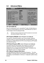
...] [3x] [4x] 66 Chapter 4: BIOS Setup The ratios that appear in the popup menu vary according to hang or crash! CPU / Memory Frequency Ratio [Auto] This field determines whether the memory clock frequency. 4.4 Advanced Menu CPU Speed [Manual] When the motherboard is set to JumperFree™ mode, this field allows you to...
...] [3x] [4x] 66 Chapter 4: BIOS Setup The ratios that appear in the popup menu vary according to hang or crash! CPU / Memory Frequency Ratio [Auto] This field determines whether the memory clock frequency. 4.4 Advanced Menu CPU Speed [Manual] When the motherboard is set to JumperFree™ mode, this field allows you to...


