
English Manual
Page 1
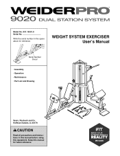
Model No. 831.15501.0 Serial No. Write the serial number in this manual before using this manual for reference. WEIGHT SYSTEM EXERCISER User’'s Manual Serial Number Decal •• Assembly •• Operation •• Maintenance •• Part List and Drawing Sears, Roebuck and Co. Hoffman Estates, IL 60179 CAUTION Read all precautions and instructions in the space above for future reference. Keep this equipment.
Model No. 831.15501.0 Serial No. Write the serial number in this manual before using this manual for reference. WEIGHT SYSTEM EXERCISER User’'s Manual Serial Number Decal •• Assembly •• Operation •• Maintenance •• Part List and Drawing Sears, Roebuck and Co. Hoffman Estates, IL 60179 CAUTION Read all precautions and instructions in the space above for future reference. Keep this equipment.

English Manual
Page 2
...: The decal(s) may not be shown at actual size. 2 TABLE OF CONTENTS WARNING DECAL PLACEMENT 2 IMPORTANT PRECAUTIONS 3 BEFORE YOU BEGIN 4 PART IDENTIFICATION CHART 5 ASSEMBLY 7 ADJUSTMENT 37 WEIGHT RESISTANCE CHART 39 CABLE DIAGRAMS 40 MAINTENANCE 42 EXERCISE GUIDELINES 43 PART LIST 47 EXPLODED DRAWING 49 ORDERING REPLACEMENT PARTS Back Cover 90 DAY FULL WARRANTY Back Cover WARNING DECAL PLACEMENT This drawing shows the location(s) of the warning decal(s). If a decal is...
...: The decal(s) may not be shown at actual size. 2 TABLE OF CONTENTS WARNING DECAL PLACEMENT 2 IMPORTANT PRECAUTIONS 3 BEFORE YOU BEGIN 4 PART IDENTIFICATION CHART 5 ASSEMBLY 7 ADJUSTMENT 37 WEIGHT RESISTANCE CHART 39 CABLE DIAGRAMS 40 MAINTENANCE 42 EXERCISE GUIDELINES 43 PART LIST 47 EXPLODED DRAWING 49 ORDERING REPLACEMENT PARTS Back Cover 90 DAY FULL WARRANTY Back Cover WARNING DECAL PLACEMENT This drawing shows the location(s) of the warning decal(s). If a decal is...
English Manual
Page 3
.... Never release the arms, leg lever, lat bar, leg press, ab strap, or handle while weights are on the weight system. Make sure that the cables are raised. The weight system should not be used by or through the use only. Before beginning any worn parts immediately. 8. tem. The weight system is the responsibility of the owner to increase the resistance. 4. caught on the pulleys. Keep hands and...
.... Never release the arms, leg lever, lat bar, leg press, ab strap, or handle while weights are on the weight system. Make sure that the cables are raised. The weight system should not be used by or through the use only. Before beginning any worn parts immediately. 8. tem. The weight system is the responsibility of the owner to increase the resistance. 4. caught on the pulleys. Keep hands and...
English Manual
Page 4
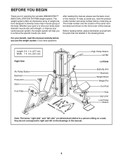
...) Right Side Ab Pulley Station Backrest Press Arm Seat Foot Plate High Pulley Station Lat Bar Left Side Butterfly Arm Backrest Weight Stack Weight Pin Curl Pad Seat Leg Lever Low Pulley Station Note: The terms “"right side”" and “"left side”" are determined relative to develop every major muscle group of the body. The model number and the location of the serial number decal are labeled...
...) Right Side Ab Pulley Station Backrest Press Arm Seat Foot Plate High Pulley Station Lat Bar Left Side Butterfly Arm Backrest Weight Stack Weight Pin Curl Pad Seat Leg Lever Low Pulley Station Note: The terms “"right side”" and “"left side”" are determined relative to develop every major muscle group of the body. The model number and the location of the serial number decal are labeled...

English Manual
Page 5
... not in parentheses below to see if it has been preassembled. Extra parts may be included. If a part is the key number of the part, from the PART LIST near the end of this manual. The number in the hardware kit, check to identify the small parts needed for assembly. PART IDENTIFICATION CHART Use the drawings below each drawing is missing, please call 1-877-992...
... not in parentheses below to see if it has been preassembled. Extra parts may be included. If a part is the key number of the part, from the PART LIST near the end of this manual. The number in the hardware kit, check to identify the small parts needed for assembly. PART IDENTIFICATION CHART Use the drawings below each drawing is missing, please call 1-877-992...
English Manual
Page 7
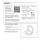
... right parts are marked “"R”" or “"Right.”" •• To identify small parts, see page 5. •• In addition to the included tool(s), assembly requires the following tool(s): one Phillips screwdriver two adjustable wrenches one rubber mallet Assembly may be used. ASSEMBLY •• To watch an assembly video, go to http://productvideo.co/ assembly/sears/weider or use power tools...
... right parts are marked “"R”" or “"Right.”" •• To identify small parts, see page 5. •• In addition to the included tool(s), assembly requires the following tool(s): one Phillips screwdriver two adjustable wrenches one rubber mallet Assembly may be used. ASSEMBLY •• To watch an assembly video, go to http://productvideo.co/ assembly/sears/weider or use power tools...

English Manual
Page 16
... Butterfly Arm (23). 18. Attach the Lat Bar Bracket (15) to identify the cables. 19 Locate Cable B (64). Locate the two wire ties in the center of Cable B are under the rods in the Swivel Brackets. Make sure to each end of Cable B (64) through the Butterfly Arm. See the CABLE DIAGRAMS starting on page 40 to the Left Upright (14) with two M10 x 68mm Bolts (98...
... Butterfly Arm (23). 18. Attach the Lat Bar Bracket (15) to identify the cables. 19 Locate Cable B (64). Locate the two wire ties in the center of Cable B are under the rods in the Swivel Brackets. Make sure to each end of Cable B (64) through the Butterfly Arm. See the CABLE DIAGRAMS starting on page 40 to the Left Upright (14) with two M10 x 68mm Bolts (98...

English Manual
Page 20
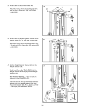
.... Route Cable C (65) under a Pulley (46). 29 Attach the Pulley (46) and a Cable Trap (49) to the Left Seat Frame (18) with an M10 x 75mm Bolt (113), two M10 Washers (93), two 16mm Spacers (100), and an M10 Locknut (84). 15 Rod 100 93 84 46 65 100 93 113 29. Route Cable C through the Lat Bar Bracket (15). See the CABLE DIAGRAMS starting on...
.... Route Cable C (65) under a Pulley (46). 29 Attach the Pulley (46) and a Cable Trap (49) to the Left Seat Frame (18) with an M10 x 75mm Bolt (113), two M10 Washers (93), two 16mm Spacers (100), and an M10 Locknut (84). 15 Rod 100 93 84 46 65 100 93 113 29. Route Cable C through the Lat Bar Bracket (15). See the CABLE DIAGRAMS starting on...
English Manual
Page 25
... 84 66 50 A 28 A 53 Then, tighten an M10 Locknut (84) onto the end of Cable D (66) into the Weight Selector Bumper (50) and the Weight Selector (28). 39. Set the Weight Selector Bumper (50) on the Weight Stack Top (13) and over a Pulley (46). See the inset drawing. Locate the bolt (A) attached to the Weight Stack Top (13) with an M10...
... 84 66 50 A 28 A 53 Then, tighten an M10 Locknut (84) onto the end of Cable D (66) into the Weight Selector Bumper (50) and the Weight Selector (28). 39. Set the Weight Selector Bumper (50) on the Weight Stack Top (13) and over a Pulley (46). See the inset drawing. Locate the bolt (A) attached to the Weight Stack Top (13) with an M10...

English Manual
Page 27
.... Attach the Pulley (46) with four ST4.2 x 16mm Screws (90). See step 12. Insert a Pulley (46) into the Press Arm Bracket (25) under Cable E (67). Attach a Frame Cap (40) to the Press Arm Bracket (25) with an M10 x 75mm Bolt (113), two M10 Washers (93), two 16mm Spacers (100), and an M10 Locknut (84). 44. Tighten the M10 x 70mm Bolts (99) used in this step. 46...
.... Attach the Pulley (46) with four ST4.2 x 16mm Screws (90). See step 12. Insert a Pulley (46) into the Press Arm Bracket (25) under Cable E (67). Attach a Frame Cap (40) to the Press Arm Bracket (25) with an M10 x 75mm Bolt (113), two M10 Washers (93), two 16mm Spacers (100), and an M10 Locknut (84). 44. Tighten the M10 x 70mm Bolts (99) used in this step. 46...
English Manual
Page 35
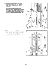
... and Left Uprights (2, 14), attach four Shroud Fasteners (44) in the indicated locations with eight ST4.2 x 16mm Screws (90); While a second person holds the Upper Shroud (31) against the Right and Left Uprights (2, 14), attach two Shroud Fasteners (44) in the indicated locations with four ST4.2 x 16mm Screws (90); the Upper Shroud (not shown) has a “"WEIDER PRO”" decal...
... and Left Uprights (2, 14), attach four Shroud Fasteners (44) in the indicated locations with eight ST4.2 x 16mm Screws (90); While a second person holds the Upper Shroud (31) against the Right and Left Uprights (2, 14), attach two Shroud Fasteners (44) in the indicated locations with four ST4.2 x 16mm Screws (90); the Upper Shroud (not shown) has a “"WEIDER PRO”" decal...
English Manual
Page 36
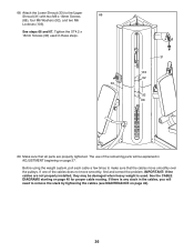
Attach the Lower Shroud (33) to make sure that all parts are not properly installed, they may be explained in the cables, you will need to remove the slack by tightening the cables (see MAINTENANCE on page 40 for proper cable routing. See steps 66 and 67. Make sure that the cables move smoothly, find and correct the problem. If there is used in these steps. 33 31 103...
Attach the Lower Shroud (33) to make sure that all parts are not properly installed, they may be explained in the cables, you will need to remove the slack by tightening the cables (see MAINTENANCE on page 40 for proper cable routing. See steps 66 and 67. Make sure that the cables move smoothly, find and correct the problem. If there is used in these steps. 33 31 103...
English Manual
Page 37
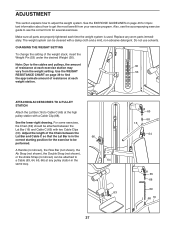
CHANGING THE WEIGHT SETTING To change the setting of resistance at each weight station. Do not use solvents. ATTACHING ACCESSORIES TO A PULLEY STATION Attach the Lat Bar (16) to get the most benefit from the weight setting. See the EXERCISE GUIDELINES on page 39 to the cables and pulleys, the amount of the weight stack, insert the Weight Pin (53) under the desired Weight (30). Also, see the correct form for the exercise to a Cable (63...
CHANGING THE WEIGHT SETTING To change the setting of resistance at each weight station. Do not use solvents. ATTACHING ACCESSORIES TO A PULLEY STATION Attach the Lat Bar (16) to get the most benefit from the weight setting. See the EXERCISE GUIDELINES on page 39 to the cables and pulleys, the amount of the weight stack, insert the Weight Pin (53) under the desired Weight (30). Also, see the correct form for the exercise to a Cable (63...

English Manual
Page 38
... To lock the weight stack, insert the Lock Pin (73) through a Weight Guide (29), and secure the Lock (74) onto the Lock Pin. 38 37 21 42 18 29 73 74 Then, tighten the Adjustment Knob. 39 42 USING THE CURL PAD To use the Curl Pad (37), first loosen the indicated Adjustment Knob (42). Next, pull the Adjustment Knob, move the Long Backrest to...
... To lock the weight stack, insert the Lock Pin (73) through a Weight Guide (29), and secure the Lock (74) onto the Lock Pin. 38 37 21 42 18 29 73 74 Then, tighten the Adjustment Knob. 39 42 USING THE CURL PAD To use the Curl Pad (37), first loosen the indicated Adjustment Knob (42). Next, pull the Adjustment Knob, move the Long Backrest to...

English Manual
Page 39
... refer to the 10-lb. WEIGHT RESISTANCE CHART The chart below shows the approximate weight resistance at each exercise station. Note: The weight resistance shown for the butterfly arm station is for each arm. WEIGHT 1 2 3 4 5 6 7 8 9 10 11 12 13 14 15 AB STATION (lbs./kg) BUTTERFLY ARM (lbs./kg) 20 / 9...PRESS ARM (lbs./kg) 27 / 12 42 / 19 56 / 25 63 / 29 76 / 34 93 / 42 104 / 47 113 / 51 127 / 58 141 / 64 151 / 69 173 / 79 181 / 82 210 / 95 230 / 104 Note: 1 lb. = 0.45 kg 39 The numbers in individual weights as well as friction between the cables, pulleys, and weight guides. weights...
... refer to the 10-lb. WEIGHT RESISTANCE CHART The chart below shows the approximate weight resistance at each exercise station. Note: The weight resistance shown for the butterfly arm station is for each arm. WEIGHT 1 2 3 4 5 6 7 8 9 10 11 12 13 14 15 AB STATION (lbs./kg) BUTTERFLY ARM (lbs./kg) 20 / 9...PRESS ARM (lbs./kg) 27 / 12 42 / 19 56 / 25 63 / 29 76 / 34 93 / 42 104 / 47 113 / 51 127 / 58 141 / 64 151 / 69 173 / 79 181 / 82 210 / 95 230 / 104 Note: 1 lb. = 0.45 kg 39 The numbers in individual weights as well as friction between the cables, pulleys, and weight guides. weights...
English Manual
Page 42
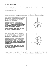
Replace any worn parts immediately. TIGHTENING THE CABLES Woven cable, the type of cable used . Remove the M10 Locknut (84) and the M10 x 50mm Bolt (102) from the Pulley (46), the Cable Trap (49), the two Half Guards (47), and the U-bracket. If a cable tends to slip off the weight stack. If the cables need to be replaced, see HOW TO ORDER REPLACEMENT PARTS on the weight system, can stretch slightly...
Replace any worn parts immediately. TIGHTENING THE CABLES Woven cable, the type of cable used . Remove the M10 Locknut (84) and the M10 x 50mm Bolt (102) from the Pulley (46), the Cable Trap (49), the two Half Guards (47), and the U-bracket. If a cable tends to slip off the weight stack. If the cables need to be replaced, see HOW TO ORDER REPLACEMENT PARTS on the weight system, can stretch slightly...
English Manual
Page 43
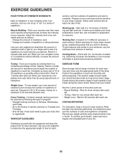
... a short period of motion for each set . •• Toning—-Rest for exercise. Record your body temperature, heart rate, and circulation in each workout with the equipment and learn the proper form for three minutes after each set . Work your life. Weight Loss—-To lose weight, use a low amount of resistance and increase the number of each set . The exertion stage of repetitions...
... a short period of motion for each set . •• Toning—-Rest for exercise. Record your body temperature, heart rate, and circulation in each workout with the equipment and learn the proper form for three minutes after each set . Work your life. Weight Loss—-To lose weight, use a low amount of resistance and increase the number of each set . The exertion stage of repetitions...
English Manual
Page 44
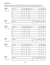
... make exercise a regular and enjoyable part of this page, and use the copies to schedule and record your life. Sets Reps Exercise 6. Exercise Lbs. Sets Reps 2. 7. 3. 8. 4. 9. 5. 10. Aerobic Date: Exercise Time Distance Speed Strength Date: Aerobic Date: Exercise 1. 2. 3. 4. 5. Exercise Lbs. EXERCISE LOG Make copies of your strength and aerobic workouts. Sets Reps Time Distance Speed 44 Lbs. Lbs. Lbs. Sets Reps Exercise 6. 7. 8. 9. 10. Sets Reps Time Distance Speed Strength Date: Aerobic Date: Exercise...
... make exercise a regular and enjoyable part of this page, and use the copies to schedule and record your life. Sets Reps Exercise 6. Exercise Lbs. Sets Reps 2. 7. 3. 8. 4. 9. 5. 10. Aerobic Date: Exercise Time Distance Speed Strength Date: Aerobic Date: Exercise 1. 2. 3. 4. 5. Exercise Lbs. EXERCISE LOG Make copies of your strength and aerobic workouts. Sets Reps Time Distance Speed 44 Lbs. Lbs. Lbs. Sets Reps Exercise 6. 7. 8. 9. 10. Sets Reps Time Distance Speed Strength Date: Aerobic Date: Exercise...
English Manual
Page 47
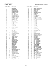
... Seat Handle Right Press Handle Left Press Handle Right Press Arm Left Press Arm Weight Stack Top Left Upright Lat Bar Bracket Lat Bar Short Base Left Seat Frame Foam Pad Tube Leg Lever Curl Pad Frame Row Bar Butterfly Arm Swivel Bracket Press Arm Bracket Pulley Plate U-bracket Weight Selector Weight Guide Weight Upper Shroud Left Seat Handle Lower Shroud Short Backrest Narrow Seat Wide Seat Curl Pad Rubber Guard Long Backrest Frame Cap Left Seat Frame Cap Adjustment Knob...
... Seat Handle Right Press Handle Left Press Handle Right Press Arm Left Press Arm Weight Stack Top Left Upright Lat Bar Bracket Lat Bar Short Base Left Seat Frame Foam Pad Tube Leg Lever Curl Pad Frame Row Bar Butterfly Arm Swivel Bracket Press Arm Bracket Pulley Plate U-bracket Weight Selector Weight Guide Weight Upper Shroud Left Seat Handle Lower Shroud Short Backrest Narrow Seat Wide Seat Curl Pad Rubber Guard Long Backrest Frame Cap Left Seat Frame Cap Adjustment Knob...
English Manual
Page 48
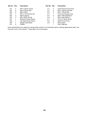
... Left Seat Frame Sleeve Weight Stack Base Handle 111 4 112 2 113 2 114 1 115 2 116 1 117 4 118 2 119 2 * —- 25mm Round Foam Grip M10 x 45mm Hex Bolt M10 x 75mm Bolt Press Arm Bracket Cap M10 x 59mm Bolt Set M10 Large Washer ST4.2 x 10mm Screw 28mm Round Cap M8 Locknut User’'s Manual Note: Specifications are not illustrated. 48 Key No. Qty. For information about ordering replacement parts...
... Left Seat Frame Sleeve Weight Stack Base Handle 111 4 112 2 113 2 114 1 115 2 116 1 117 4 118 2 119 2 * —- 25mm Round Foam Grip M10 x 45mm Hex Bolt M10 x 75mm Bolt Press Arm Bracket Cap M10 x 59mm Bolt Set M10 Large Washer ST4.2 x 10mm Screw 28mm Round Cap M8 Locknut User’'s Manual Note: Specifications are not illustrated. 48 Key No. Qty. For information about ordering replacement parts...


