
English Manual
Page 3
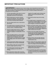
... system indoors, away from the weight system at all warnings on the pulleys at all parts regularly. Make sure that all users of this manual. 11. The weight system should not be used by or through the use the lat bar. 18. IMPORTANT PRECAUTIONS WARNING: To reduce the risk of serious...
... system indoors, away from the weight system at all warnings on the pulleys at all parts regularly. Make sure that all users of this manual. 11. The weight system should not be used by or through the use the lat bar. 18. IMPORTANT PRECAUTIONS WARNING: To reduce the risk of serious...

English Manual
Page 11
... yet. Attach a Weight Guide (29) to the Right and Left Uprights (2, 14) with the other Weight Guide (29). 84 93 13 86 93 29 85 11 Repeat this step with four M10 x 68mm Bolts (98), four M10 Washers (93), and two M10 Locknuts (84);
... yet. Attach a Weight Guide (29) to the Right and Left Uprights (2, 14) with the other Weight Guide (29). 84 93 13 86 93 29 85 11 Repeat this step with four M10 x 68mm Bolts (98), four M10 Washers (93), and two M10 Locknuts (84);

English Manual
Page 12
While a second person holds the Foot Plate (6) against the Leg Press Frame (5), insert the Foot Plate Tube (7) through the Foot Plate and the Leg Press Frame. Then, press a Foot Plate Tube Cap (62) into each end of the included grease to the Long Base (1) with the M10 x 95mm Bolt (83) and an M10 Locknut (84). the Press Frame must pivot easily. 10 5 84 1 83 Grease 11. Using a plastic bag to keep your fingers clean, apply some of the Foot Plate Tube (7). 11 62 5 6 7 62 12 Do not overtighten the Locknut; Attach the Leg Press Frame (5) to an M10 x 95mm Bolt (83). 10.
While a second person holds the Foot Plate (6) against the Leg Press Frame (5), insert the Foot Plate Tube (7) through the Foot Plate and the Leg Press Frame. Then, press a Foot Plate Tube Cap (62) into each end of the included grease to the Long Base (1) with the M10 x 95mm Bolt (83) and an M10 Locknut (84). the Press Frame must pivot easily. 10 5 84 1 83 Grease 11. Using a plastic bag to keep your fingers clean, apply some of the Foot Plate Tube (7). 11 62 5 6 7 62 12 Do not overtighten the Locknut; Attach the Leg Press Frame (5) to an M10 x 95mm Bolt (83). 10.

English Manual
Page 13
12. Do not overtighten the Locknut; the Press Arms must pivot easily. 11 84 12 83 Grease 1 13 Orient the parts 12 as shown. Identify the Right and Left Press Arms (11, 12) and the Press Arm Bracket (25). Attach the Right and Left Press Arms (11, 12) to the Long Base (1) with three M10 x 70mm Bolts (99) and three M10 Locknuts (84); do not tighten the Bolts yet. 11 84 25 84 12 99 99 13. Apply grease to an M10 x 95mm Bolt (83). 13 Attach the Right and Left Press Arms (11, 12) to the Press Arm Bracket (25) with the M10 x 95mm Bolt (83) and an M10 Locknut (84).
12. Do not overtighten the Locknut; the Press Arms must pivot easily. 11 84 12 83 Grease 1 13 Orient the parts 12 as shown. Identify the Right and Left Press Arms (11, 12) and the Press Arm Bracket (25). Attach the Right and Left Press Arms (11, 12) to the Long Base (1) with three M10 x 70mm Bolts (99) and three M10 Locknuts (84); do not tighten the Bolts yet. 11 84 25 84 12 99 99 13. Apply grease to an M10 x 95mm Bolt (83). 13 Attach the Right and Left Press Arms (11, 12) to the Press Arm Bracket (25) with the M10 x 95mm Bolt (83) and an M10 Locknut (84).

English Manual
Page 14
Attach the Right Seat Frame (4) to the Long Base (1) with the M10 x 59mm Bolt Set (115). Apply grease to an M10 x 59mm Bolt Set (115). 14 9 Attach the Left Press Handle (10) to the Right 11 Press Arm (11) in the same way. 15. Attach the Right Press Handle (9) to the Left Press Arm (12) with two M10 x 115mm Bolts (97), four 15 M10 Washers (93), and two M10 Locknuts (84); do not tighten the Bolts yet. 115 10 115 Grease 12 84 93 1 4 93 97 14 14.
Attach the Right Seat Frame (4) to the Long Base (1) with the M10 x 59mm Bolt Set (115). Apply grease to an M10 x 59mm Bolt Set (115). 14 9 Attach the Left Press Handle (10) to the Right 11 Press Arm (11) in the same way. 15. Attach the Right Press Handle (9) to the Left Press Arm (12) with two M10 x 115mm Bolts (97), four 15 M10 Washers (93), and two M10 Locknuts (84); do not tighten the Bolts yet. 115 10 115 Grease 12 84 93 1 4 93 97 14 14.

English Manual
Page 39
weights. WEIGHT 1 2 3 4 5 6 7 8 9 10 11 12 13 14 15 AB STATION (lbs./kg) BUTTERFLY ARM (lbs./kg) 20 / 9 31 / 14 42 / 19 53 / 24 66 / 30 80 / 36 93 / 42 ...
weights. WEIGHT 1 2 3 4 5 6 7 8 9 10 11 12 13 14 15 AB STATION (lbs./kg) BUTTERFLY ARM (lbs./kg) 20 / 9 31 / 14 42 / 19 53 / 24 66 / 30 80 / 36 93 / 42 ...
English Manual
Page 47
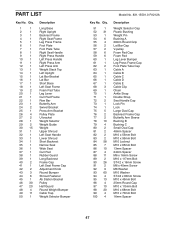
... M10 x 45mm Bolt 25mm Round Cap M10 x 115mm Bolt M10 x 68mm Bolt M10 x 70mm Bolt 16mm Spacer 47 Qty. 1 1 2 1 3 1 4 1 5 1 6 1 7 1 8 1 9 1 10 1 11 1 12 1 13 1 14 1 15 1 16 1 17 1 18 1 19 2 20 1 21 1 22 1 23 1 24 2 25 1 26 4 27 2 28 1 29 2 30 15 31 1 32 1 33... 1 34 1 35 1 36 1 37 1 38 1 39 1 40 2 41 1 42 2 43 3 44 6 45 1 46 30 47 20 48 4 49 11 50 1 Description Long Base Right Upright Backrest Frame Right Seat Frame Leg Press Frame Foot Plate Foot Plate Tube Right Seat Handle Right Press Handle...
... M10 x 45mm Bolt 25mm Round Cap M10 x 115mm Bolt M10 x 68mm Bolt M10 x 70mm Bolt 16mm Spacer 47 Qty. 1 1 2 1 3 1 4 1 5 1 6 1 7 1 8 1 9 1 10 1 11 1 12 1 13 1 14 1 15 1 16 1 17 1 18 1 19 2 20 1 21 1 22 1 23 1 24 2 25 1 26 4 27 2 28 1 29 2 30 15 31 1 32 1 33... 1 34 1 35 1 36 1 37 1 38 1 39 1 40 2 41 1 42 2 43 3 44 6 45 1 46 30 47 20 48 4 49 11 50 1 Description Long Base Right Upright Backrest Frame Right Seat Frame Leg Press Frame Foot Plate Foot Plate Tube Right Seat Handle Right Press Handle...

English Manual
Page 49
EXPLODED DRAWING A 9 47 26 46 84 26 47 49 47 11 102 46 35 76 92 91 8 84 90 107 41 98 84 93 42 75 90 49 46 84 93 84 100 90 84 79 ...
EXPLODED DRAWING A 9 47 26 46 84 26 47 49 47 11 102 46 35 76 92 91 8 84 90 107 41 98 84 93 42 75 90 49 46 84 93 84 100 90 84 79 ...
