
English Manual
Page 2
...call toll-free 1-877-992-5999, Monday through Friday, 6 a.m. Remove the PART IDENTIFICATION CHART and PART LIST/EXPLODED DRAWING before beginning assembly. until 6 p.m. Apply the decal in the center of this manual. WARNING DECAL PLACEMENT The decal shown here has been placed on ...the weight system. TABLE OF CONTENTS WARNING DECAL PLACEMENT 2 IMPORTANT PRECAUTIONS 3 BEFORE YOU BEGIN 4 ASSEMBLY 5 ADJUSTMENTS 23 WEIGHT RESISTANCE CHART 25 CABLE DIAGRAMS 26 MAINTENANCE 28 EXERCISE GUIDELINES 29 ORDERING REPLACEMENT PARTS Back Cover FULL 90-DAY WARRANTY Back Cover Note: A...
...call toll-free 1-877-992-5999, Monday through Friday, 6 a.m. Remove the PART IDENTIFICATION CHART and PART LIST/EXPLODED DRAWING before beginning assembly. until 6 p.m. Apply the decal in the center of this manual. WARNING DECAL PLACEMENT The decal shown here has been placed on ...the weight system. TABLE OF CONTENTS WARNING DECAL PLACEMENT 2 IMPORTANT PRECAUTIONS 3 BEFORE YOU BEGIN 4 ASSEMBLY 5 ADJUSTMENTS 23 WEIGHT RESISTANCE CHART 25 CABLE DIAGRAMS 26 MAINTENANCE 28 EXERCISE GUIDELINES 29 ORDERING REPLACEMENT PARTS Back Cover FULL 90-DAY WARRANTY Back Cover Note: A...
English Manual
Page 5
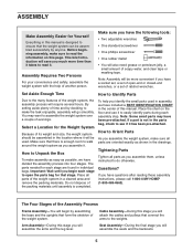
... another person. Tightening Parts Tighten all parts of ratchet wrenches. The parts needed for each assembly step. Cable Assembly-During this stage you have questions after reading these assembly instructions, please call 1-800-4-MY-HOME® (1-800-469-4663). Arm Assembly-During this stage you identify the small parts used . Place all parts as possible...
... another person. Tightening Parts Tighten all parts of ratchet wrenches. The parts needed for each assembly step. Cable Assembly-During this stage you have questions after reading these assembly instructions, please call 1-800-4-MY-HOME® (1-800-469-4663). Arm Assembly-During this stage you identify the small parts used . Place all parts as possible...
English Manual
Page 12
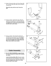
... Base (25) with the Bolt and an M10 Nylon Locknut (90). See the CABLE DIAGRAMS on the Foot Plate is right side up. the Cable must be able to pivot easily. 90 25 72 90 Grease 76 38 28 Cable Assembly 22 22. Attach the 20 Leg Press Frame (28) to the Leg Press... Frame (28) with the Bolt and an M10 Nylon Locknut (90). Do not overtighten the Locknut; Locate the Press Cable (109). Do not overtighten the Locknut; Repeat this step...
... Base (25) with the Bolt and an M10 Nylon Locknut (90). See the CABLE DIAGRAMS on the Foot Plate is right side up. the Cable must be able to pivot easily. 90 25 72 90 Grease 76 38 28 Cable Assembly 22 22. Attach the 20 Leg Press Frame (28) to the Leg Press... Frame (28) with the Bolt and an M10 Nylon Locknut (90). Do not overtighten the Locknut; Locate the Press Cable (109). Do not overtighten the Locknut; Repeat this step...
English Manual
Page 20
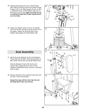
Tighten the Weight Cable (110) into the Upright and Backrest Frame, and turn it is over a 90mm Pulley 55 (63). 55...the Knob (43) into the Weight Tube (not shown) until it clockwise until all the slack is taken out of 56 the cables. Attach the Pulley and the two Quarter Finger Guards (105) to the Right Upright (2) with the other Seat (8) and the ...an M10 Washer (99), and an M10 Nylon Locknut (90). Tighten the M12 Nut (49) on the Weight Cable against the M12 Washer (33). 90 99 107 2 Rod 105 63 105 72 110 33 49 Seat Assembly 57 26 88 53 113 57. Wrap the Ab...
Tighten the Weight Cable (110) into the Upright and Backrest Frame, and turn it is over a 90mm Pulley 55 (63). 55...the Knob (43) into the Weight Tube (not shown) until it clockwise until all the slack is taken out of 56 the cables. Attach the Pulley and the two Quarter Finger Guards (105) to the Right Upright (2) with the other Seat (8) and the ...an M10 Washer (99), and an M10 Nylon Locknut (90). Tighten the M12 Nut (49) on the Weight Cable against the M12 Washer (33). 90 99 107 2 Rod 105 63 105 72 110 33 49 Seat Assembly 57 26 88 53 113 57. Wrap the Ab...
English Manual
Page 26
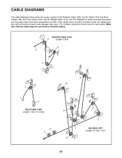
...), the Ab Cable (107), the Short Cable (108), the Press Cable (109), and the Weight Cable (110). If the cables have been assembled correctly. CABLE DIAGRAMS The cable diagrams below show the correct route for each cable. Use the diagrams to make sure that the cable traps do not touch or bind the cables. Butterfly Cable (106) 4 Length: 5 feet 2 5 1 3 2 1 3 Short Cable (108) Length...
...), the Ab Cable (107), the Short Cable (108), the Press Cable (109), and the Weight Cable (110). If the cables have been assembled correctly. CABLE DIAGRAMS The cable diagrams below show the correct route for each cable. Use the diagrams to make sure that the cable traps do not touch or bind the cables. Butterfly Cable (106) 4 Length: 5 feet 2 5 1 3 2 1 3 Short Cable (108) Length...


